In depth
One vessel, two duties
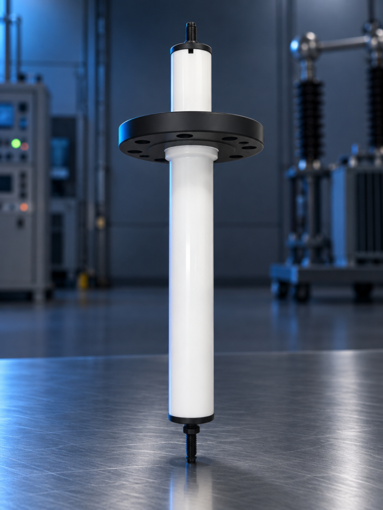
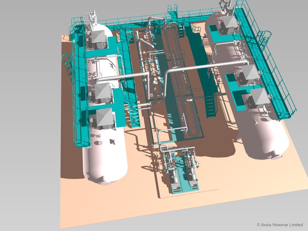
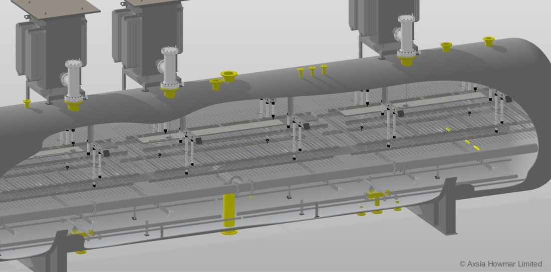
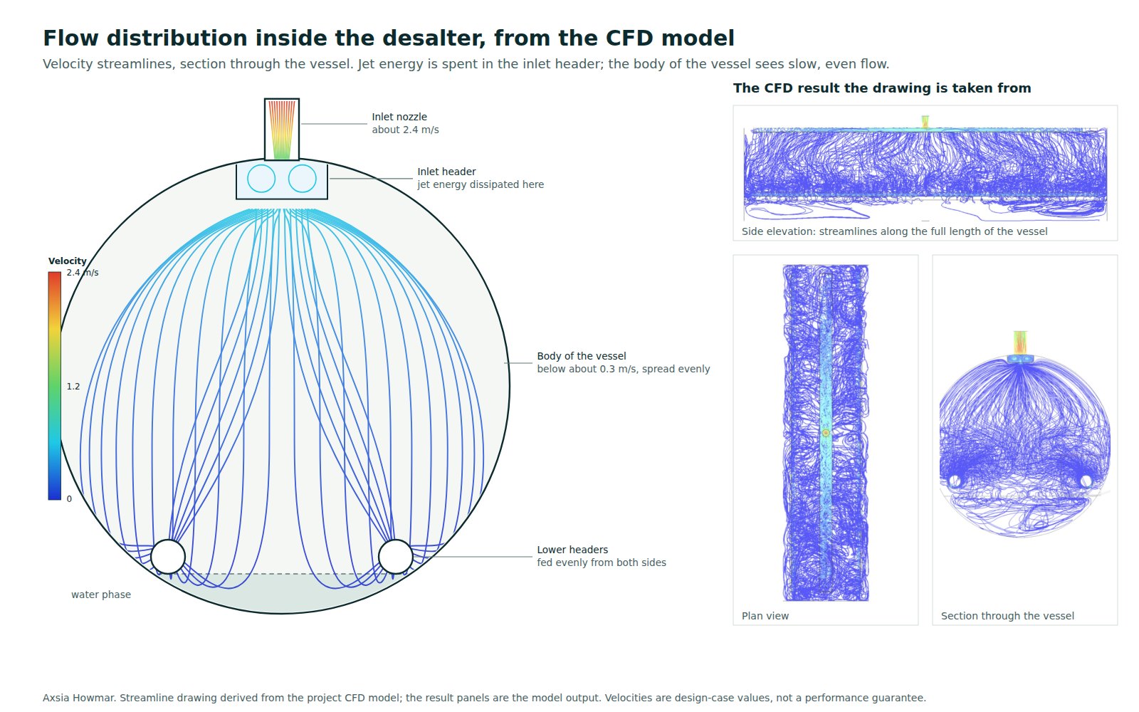
The crude oil desalter and the crude oil dehydrator are one piece of equipment. A horizontal pressure vessel holds one or more electrode grids hung on insulators above a crude distributor. Power units mounted on the vessel energise the grids at high voltage through entrance bushings that carry the conductor across the pressure boundary. Wet crude enters below the grids, the field merges the water droplets into drops that settle, treated crude leaves from the top and water leaves from the bottom under interface control.
Run without wash water, the vessel is a dehydrator: it removes the produced water in the crude so that the crude meets its basic sediment and water (BS&W) specification. Salt falls in step, because it is dissolved in the water removed, but the target is the water content. Run with low-salinity wash water mixed into the crude upstream, the same vessel is a desalter: the wash water dilutes the brine droplets before the field removes them, so the small amount of water left behind carries far less salt. In a refinery the vessel is almost always in desalter duty. At a production facility it is usually a dehydrator, sometimes followed by a desalter stage to meet an export salt specification. The naming is explained in crude oil desalter vs dehydrator.
Desalter duty
What makes a desalter is the wash water system. Low-salinity water, typically 3 to 10 vol% of the crude, is injected upstream of a mixing valve and sometimes partly upstream of the preheat exchangers. The pressure drop across the mixing valve shears the water into droplets that collide with and dilute the brine droplets already in the crude. The valve setting is a balance: too little pressure drop and the wash water never contacts the brine, too much and the mixture becomes an emulsion the vessel cannot break within its residence time. In practice the setting is found by step tests on the running unit while watching outlet salt and BS&W together.
Wash water quality matters as much as its rate. Stripped sour water, condensate and treated produced water are all used; each brings ammonia, sulphides, phenols or solids that change the emulsion and the effluent. Where a single stage cannot meet the salt specification, two vessels are run in series with the water in counter-current, fresh to the second stage and recycled to the first, as described in single-stage vs two-stage desalting.
Dehydrator duty
Dehydrator duty differs in three ways. There is no wash water or mixing valve, so the emulsion arriving at the vessel is the natural one from the wells. The inlet water cut is higher and more variable, because it follows the wells, and the design must state the maximum water cut the grids will tolerate and the point at which free-water removal is added upstream. And the target is a water content, not a salt content. The vessel sits after the low-pressure separator and the heater and before storage, export pumps or a desalter stage. Heating is the main operating cost, so the treating temperature is chosen as the lowest that meets specification with a sensible demulsifier dose; see crude oil heaters.
Inside the vessel
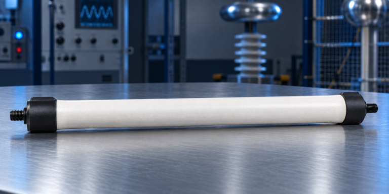
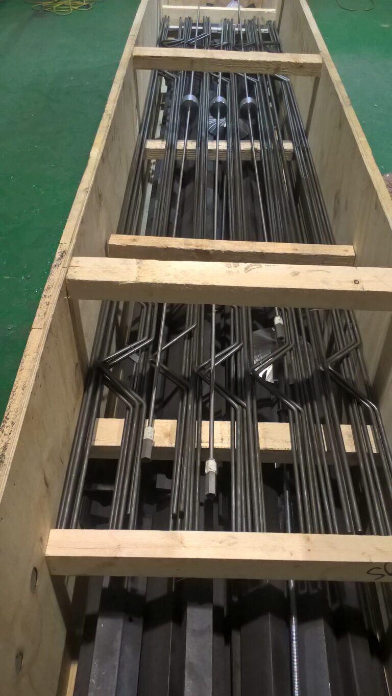
The internals are the same in both duties: the inlet distributor, the electrode grids, the insulators and the connecting rods that hang them, the entrance bushings and the interface, mud wash and drain connections. A single-grid design uses one power unit per vessel; larger vessels use three grids with three power units. The components, with an annotated drawing, are described on the electrostatic coalescers page, and the spare parts for any make of vessel on the electrostatic coalescer spare parts page.
Desalter power units
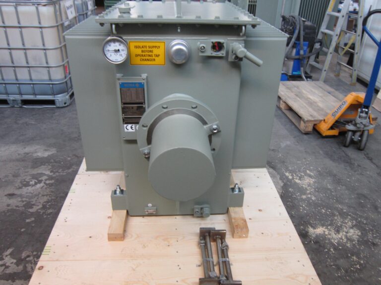
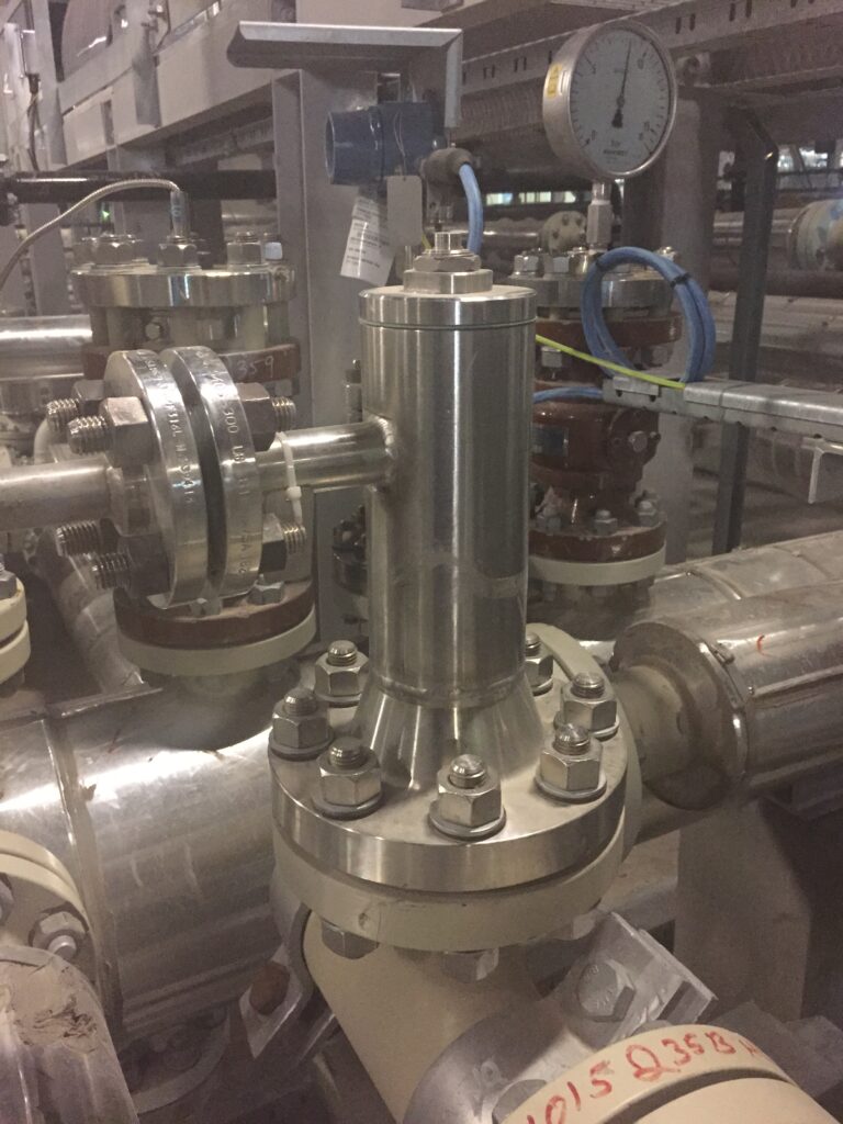
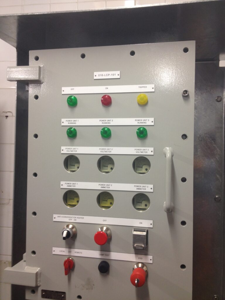
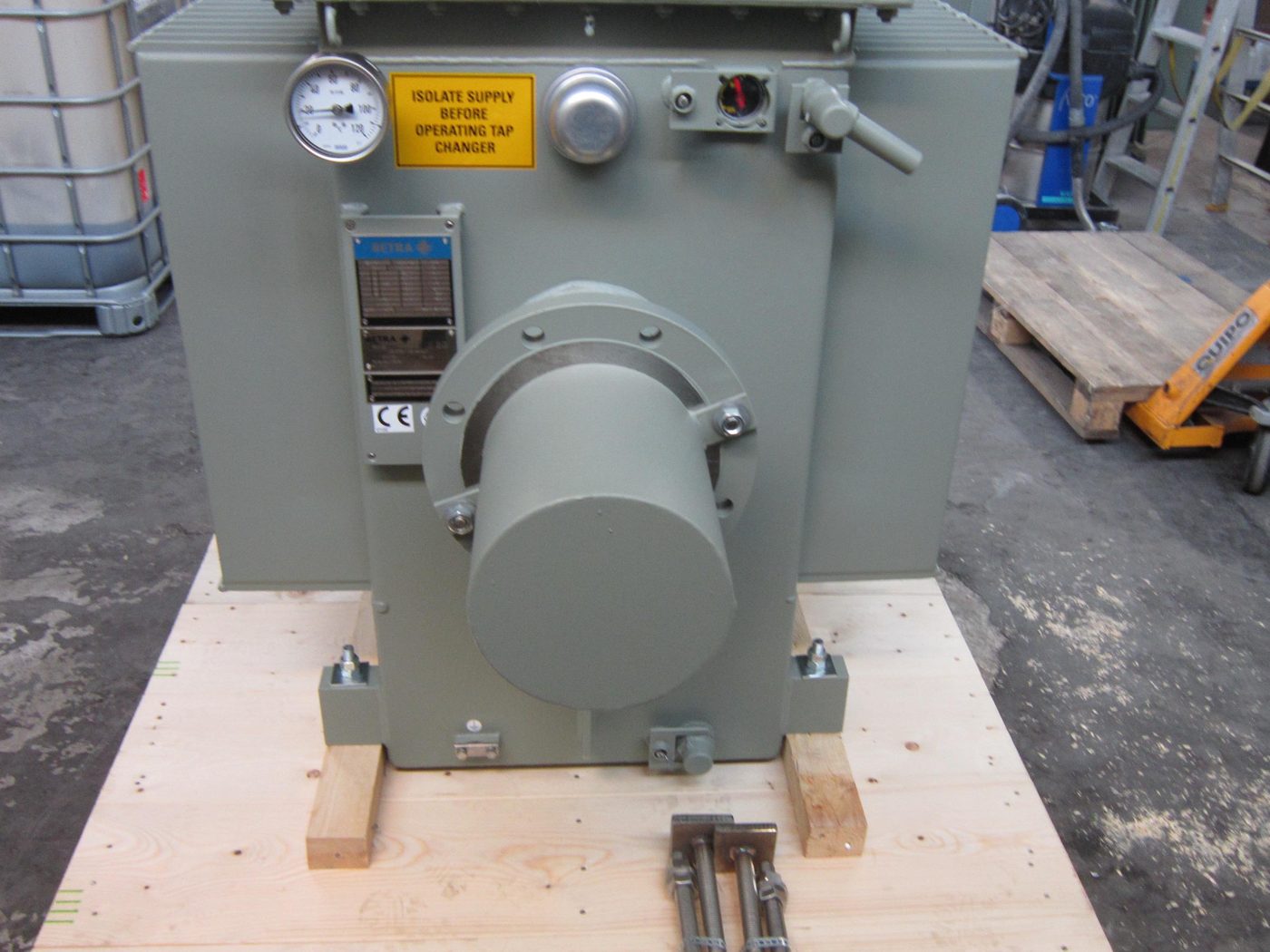
The grids are energised by desalter power units: oil-filled transformers, in a hazardous-area enclosure, that step the plant supply up to the grid voltage and limit the current when the emulsion between the grids conducts. The transformer output reaches the grid through a bushing housing, a tee-shaped spool piece filled with insulating oil that carries the high-voltage conductor from the transformer down into the entrance bushing on the vessel. The ratings, the configurations available and the bushing housing are described on the desalter power units page.
Design considerations
The design turns on the crude, the specification and how both will change. For a refinery that means the range of crudes in the slate, the salt and BS&W specification and the wash water available. For a production facility it means the water cut profile over field life, viscosity at treating temperature, emulsion stability from bottle tests and solids loading. From these the process design sets the stage count, the vessel size and grid area, the treating temperature and pressure, the wash water and recycle scheme, the power unit rating and the interface control. Axsia Howmar designs and manufactures the package and subcontracts fabrication to approved and audited fabricators under our supervision.
Common operating problems
The usual problems are high outlet BS&W or salt, grid voltage collapsing when a wet slug arrives, power units tripping, and rag layer growth fed by solids and production chemicals. Slugging from upstream, a change of crude or wash water, a fouled or damaged grid and a failed entrance bushing account for most cases. Symptoms, probable causes and the data needed to confirm them are in the troubleshooting symptom index. When the duty has moved beyond the design basis, a design review compares the options: more free-water removal upstream, higher temperature, new grids and power units within the existing shell, or a second vessel.