
Hydrogen purification

PSA hydrogen purification

Pressure swing adsorption (PSA) purifies hydrogen by passing a hydrogen-rich gas through beds of adsorbent at high pressure. Impurities are held on the adsorbent while hydrogen passes through. Each bed is then regenerated by lowering its pressure. Several beds cycle in sequence to give a continuous product, typically at 99.9 to 99.999 mol% hydrogen.

Product hydrogen purity achievable from a hydrogen-rich feed
Above 99.999 %
Single-train capacity, about 90 MMscfd, with multiple adsorbers
Over 100,000 Nm³/h
Every PSA cycle reduces to adsorption, two depressurisations, purge and repressurisation
5 steps

Send a technical enquiry

How it works: PSA hydrogen purification

  1. Adsorption

    Feed gas flows up through the bed at feed pressure. Water, carbon dioxide, hydrocarbons, carbon monoxide and nitrogen adsorb in layers; hydrogen leaves the top as product.

  2. Co-current depressurisation and pressure equalisation

    Before impurities break through, feed stops. Hydrogen left in the bed's void space is passed to other beds to repressurise and purge them, which is what recovers it.

  3. Counter-current blowdown

    The bed is depressurised from the feed end to tail gas pressure. Most of the impurities desorb and leave as tail gas.

  4. Purge

    A small flow of hydrogen from another bed sweeps the remaining impurities out at low pressure.

  5. Repressurisation

    The bed is brought back to feed pressure with equalisation gas and product, ready for the next adsorption step.

The process

Impurities held at high pressure, released at low pressure

Pressure swing adsorption (PSA) adsorbs the impurities from a hydrogen-rich feed gas onto a fixed bed of adsorbents at high pressure, then desorbs them at low pressure into an off-gas stream, leaving an extremely pure hydrogen product. Purities in excess of 99.999 % can be reached. Feeds include steam reformer syngas, methanol cracker syngas, refinery gases, ethylene cracker gas and coke oven gas; users include propane dehydrogenation, linear alkyl benzene and gas-to-liquids plants, and the many refinery processes that need clean hydrogen to cut sulphur and aromatics.

The process is a batch operation, but continuous product and off-gas flows are achieved by running several adsorbers in a stepwise sequence. However complex the cycle, it always reduces to five steps: adsorption; co-current depressurisation, which passes hydrogen from the void spaces into beds that are repressurising; counter-current depressurisation, which blows the impurities down into the off-gas; purge at low pressure with hydrogen-rich gas from another adsorber; and counter-current repressurisation with recovered gas and product. For higher recoveries or larger throughputs, more adsorbers are added; several beds share the adsorption step to reduce vessel size and adsorbent quantity, and a single train can exceed 100,000 Nm³/h.

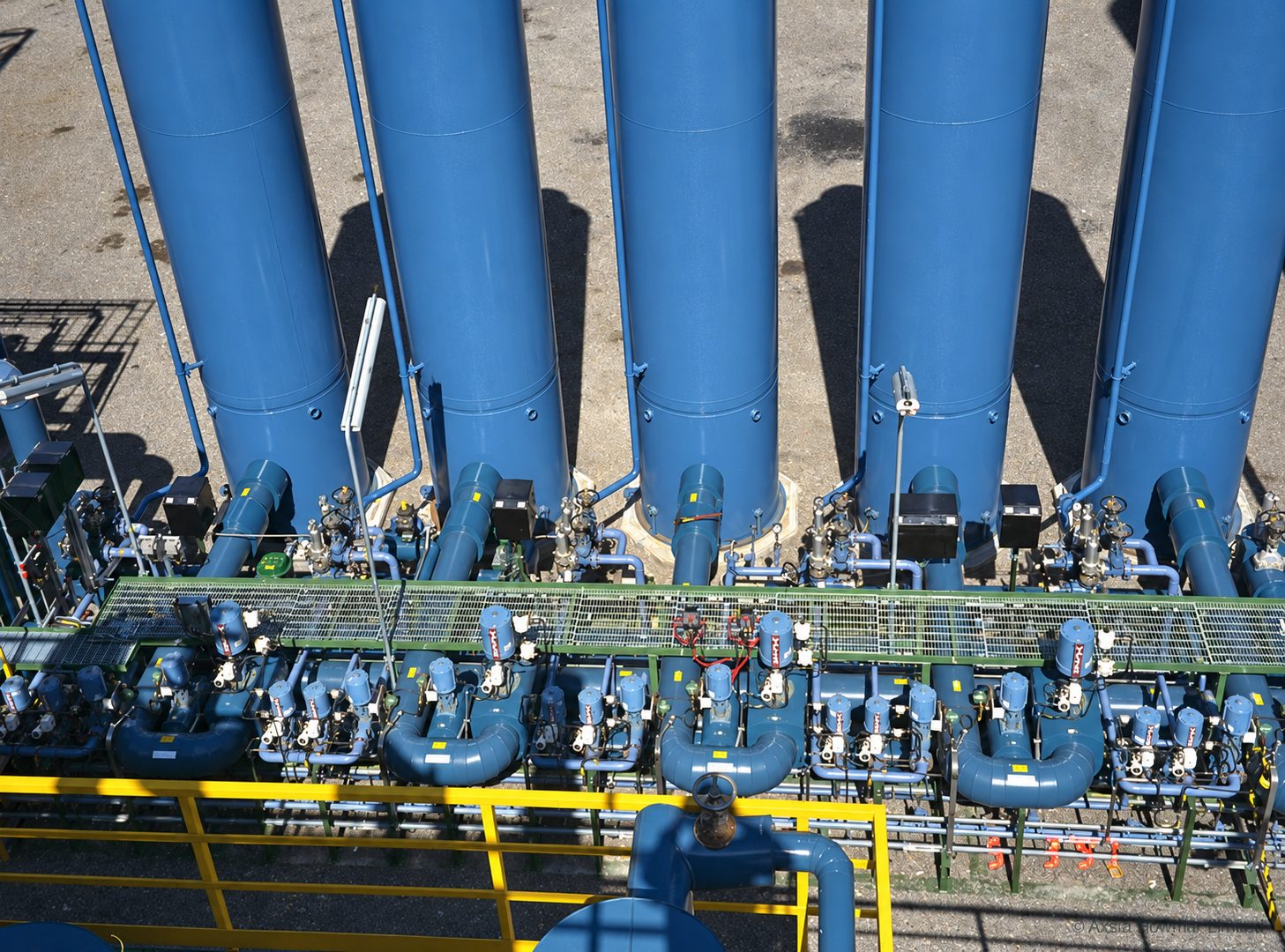
Adsorber vessels and the valve skid of a multi-bed hydrogen PSA unit: each vessel is switched through the cycle by its own set of automated valves.

Dynamic modelling

The cycle is designed on a dynamic model, not a rule of thumb

A PSA bed never reaches steady state: pressure, flow and the concentration front of each impurity move through every adsorber on every step. Axsia Howmar designs the cycle with a dynamic model of the whole unit that follows carbon dioxide, carbon monoxide, methane and nitrogen through the bed layers, step by step, and predicts the breakthrough curve of each impurity at the product end. Bed size, adsorbent layering, step times, purge ratio and the pressure equalisation sequence are then set against the real feed composition and the purity and recovery required, rather than against generic tables.

The same model is used on operating plants. It lets us extend the operating envelope of new designs, re-tune existing units for a changed feed or a higher throughput, and check a proposed cycle change before it is loaded to the controller. Continual development of the model has steadily improved plant performance and efficiency.

Valve skid fabrication

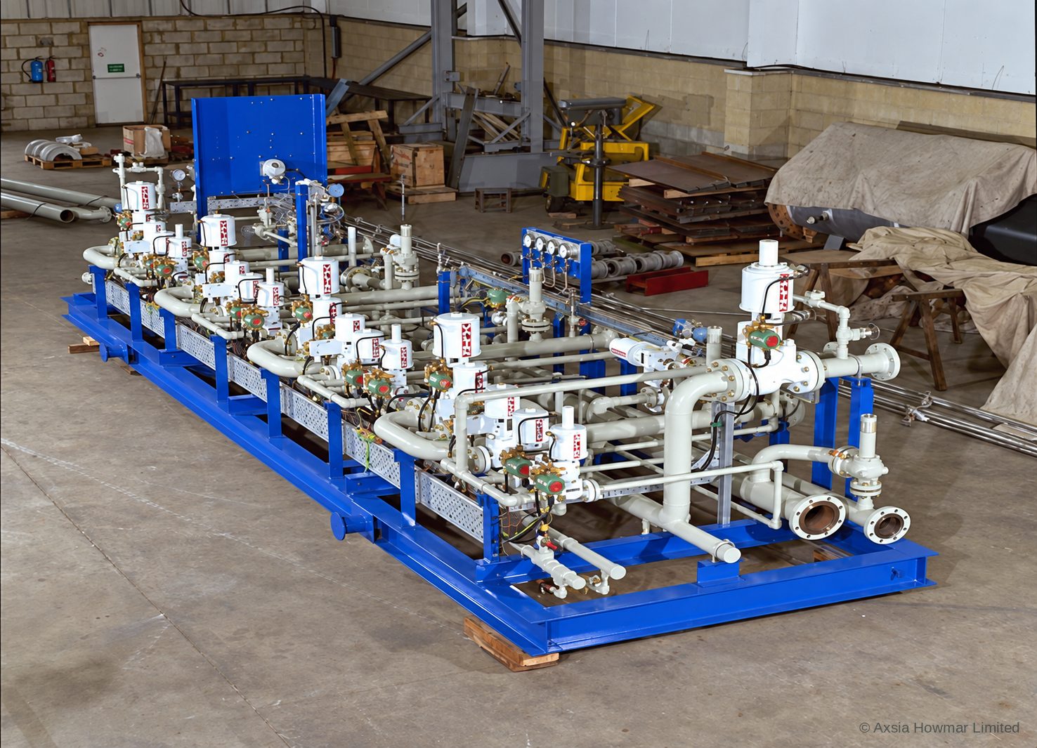
The valve skid: the heart of the unit, built and tested in the workshop

The switching valves, their actuators, the instrumentation and the interconnecting manifolds are mounted on one valve skid. It is the part of a PSA unit that does the work: every step of the cycle is a set of valve movements, and a large unit makes hundreds of thousands of them a year. The skid is designed in a 3D model with the adsorber vessels, so nozzle positions, valve orientation and access for maintenance are fixed before fabrication.

The skid is fabricated by an approved and audited fabricator under our project management and supervision, then pressure tested, loop checked and cycle tested with the control system in the workshop, so that the sequence is proven before the skid leaves.

Hydrogen PSA valve skid in the workshop: switching valves with actuators, manifolds, instrument bridges and local panel on one frame, ready for testing.

Delivery to site

Delivered as tested modules for rapid installation

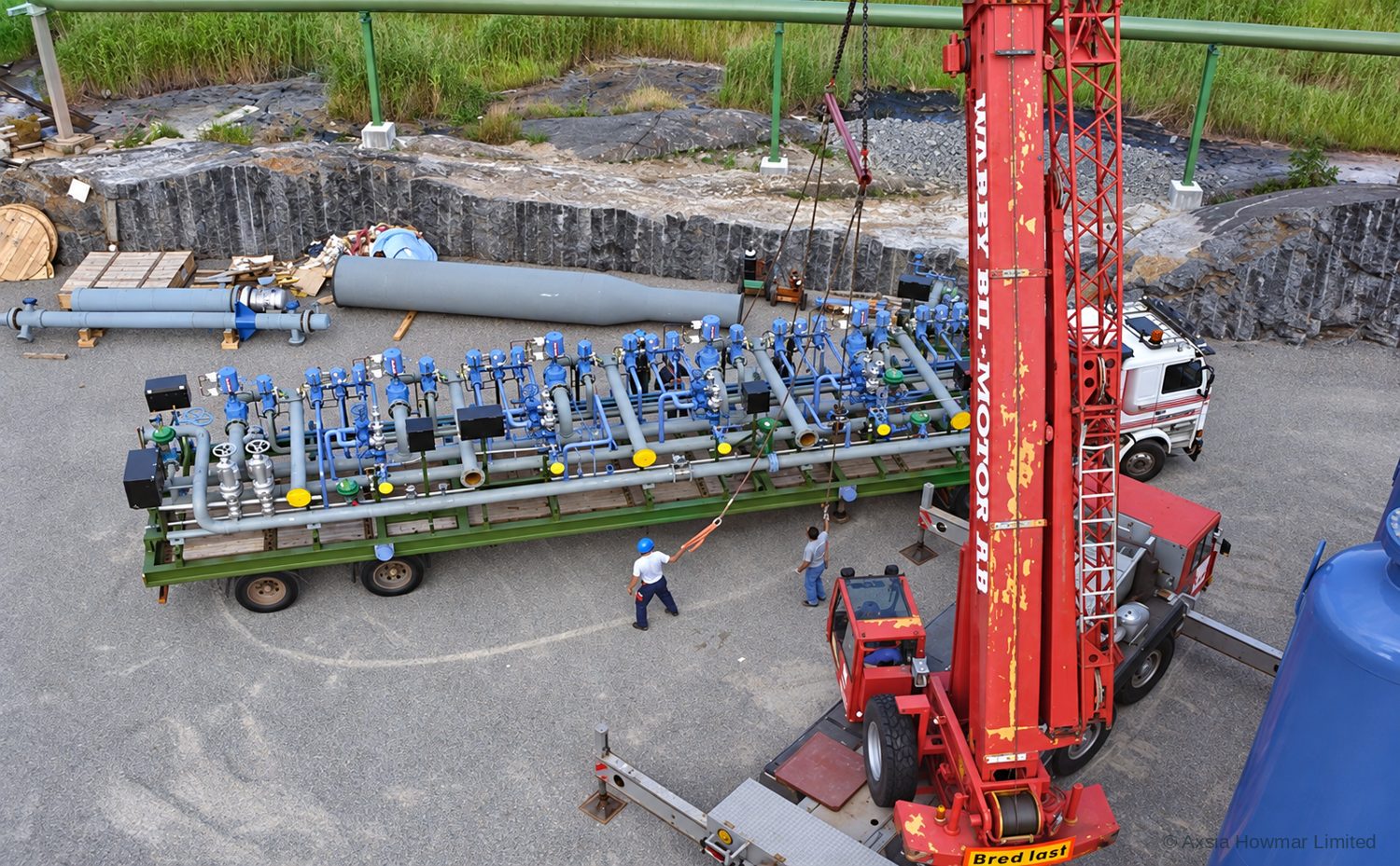
The valve skid, the adsorber vessels and the off-gas drums travel to site as separate modules and are set on the client's prepared foundations. Because the skid arrives tested, site work is limited to setting, connecting the vessels and the battery-limit piping, and terminating the control cables, which keeps the installation window short.

The PSA sequence is run by a programmable logic controller (PLC) that drives the switching valves in a predetermined order and is continually tuned for changes in feed flow and composition. Plant diagnostics identify a developing problem, locate its source and alert the operator, and if required the unit can run on a reduced number of adsorbers so that a vessel or valve can be maintained on line.

Hydrogen PSA valve skid arriving at site on a low-loader and being lifted onto its foundation.

In service

From standalone PSA to the complete hydrogen plant

PSA units of this design run on refinery and petrochemical hydrogen plants in Europe and elsewhere. Axsia Howmar supplies standalone PSA units for purification and can also integrate the PSA with a steam reformer or methanol cracker, so that the complete hydrogen plant is designed as one system. We also review, re-tune and supply adsorbents and spare parts for existing PSA units, including units built by others.

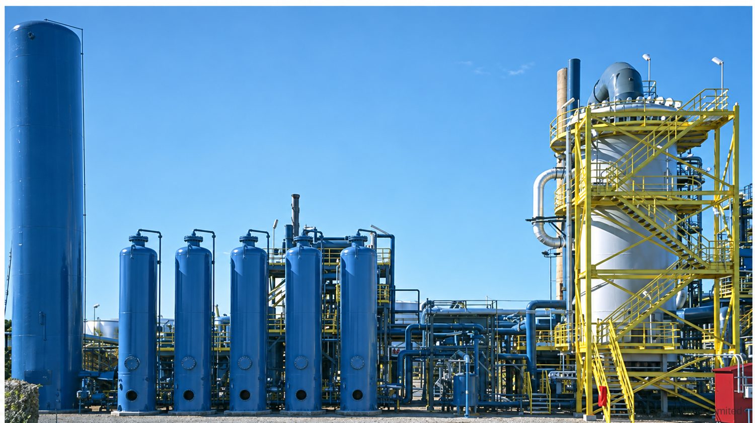
Hydrogen plant with a multi-bed PSA unit: adsorber vessels in the foreground, off-gas surge drum at left and the steam reformer behind.

Where a hydrogen PSA sits in the process

A hydrogen PSA unit is normally the last process step before hydrogen goes to its user. In a steam methane reformer plant it follows the shift converter and process gas cooling. In off-gas recovery it follows feed compression, cooling and liquid removal. Whatever the source, the feed must reach the beds free of liquid: a knock-out drum and usually a coalescing filter stand immediately upstream.

Design and selection considerations for hydrogen PSA units

The design of a hydrogen PSA unit balances purity, recovery and capital cost. The decisions that set that balance are:

  • Number of beds and equalisation steps. Each pressure equalisation saves hydrogen that would otherwise leave as tail gas. More beds allow more equalisations and higher recovery, at higher cost.
  • Adsorbent layering. Layer heights follow the feed. A feed rich in carbon dioxide needs more carbon; a tight carbon monoxide or nitrogen limit needs more molecular sieve.
  • Tail gas pressure. Lower tail gas pressure regenerates the bed more completely and raises recovery, but the tail gas user sets the minimum.
  • Vessel fatigue. A PSA vessel sees a full pressure cycle every few minutes, which is millions of cycles over its life. Fatigue governs the mechanical design.
  • Valves. Switching valves see the same cycle count and must stay tight. Their reliability decides the unit’s availability.
  • Bed hold-down and gas velocity. Upward velocity during depressurisation must stay below the level that lifts or fluidises the bed, or the adsorbent attrits to dust.

Materials used in hydrogen PSA units

Hydrogen PSA adsorber vessels are normally carbon steel, designed for cyclic service. Piping and valves follow the hydrogen service specification of the plant. Material selection for hydrogen service at the operating temperature and pressure follows the project’s piping and materials specifications.

Common operating problems with hydrogen PSA units

The common operating problems with hydrogen PSA units are declining product purity, declining recovery, rising bed pressure drop and shortened adsorbent life. Valve leakage and slow valve stroking are the most frequent mechanical causes; liquid carry-over is the most frequent process cause. Each symptom has its own entry in the troubleshooting symptom index: declining purity, rising bed pressure drop and shortened adsorbent life.

Capacity enhancement and revamp options for hydrogen PSA units

An existing hydrogen PSA unit can often deliver more product or higher recovery without new vessels. Options include re-optimising the cycle for the current feed, replacing adsorbent with a loading matched to today’s composition, replacing worn switching valves, upgrading the control system to add equalisation steps or reduced-bed modes, and lowering tail gas pressure. See design review for capacity enhancement.

Design parameters: PSA hydrogen purification

Design parameters: PSA hydrogen purification
ParameterTypical rangeUnitBasis / note
Feed pressure10 to 40bargTypical published range; gauge pressure
Feed temperature20 to 45°CTypical published range; capacity falls as temperature rises
Feed hydrogen content50 to 95mol%Typical published range
Tail gas pressure0.2 to 0.5bargTypical published range; lower pressure improves recovery
Number of beds4 to 12bedsTypical published range; more beds allow more equalisation steps

Typical ranges for orientation only. The design basis for each unit is set from the feed analysis and the required product specification.

Performance we design to: PSA hydrogen purification

Performance we design to: PSA hydrogen purification
MetricValue or rangeUnitConditions / design basis
Product purity99.9 to 99.999mol% hydrogenTypical published range
Hydrogen recovery70 to 90%Typical published range; hydrogen in product divided by hydrogen in feed

Achievable performance depends on feed conditions and the agreed design basis. These figures are design targets, not guarantees independent of those conditions.

Codes and standards applied to PSA hydrogen purification

Typically applied; the governing codes are confirmed per project with the client and the jurisdiction.

ASME BPVC Section VIII Division 1
Pressure vessels Adsorber vessels, designed for cyclic service
PD 5500 / EN 13445
Unfired pressure vessels Where specified
IEC 60079 / ATEX / IECEx
Equipment for explosive atmospheres Valves, actuators, instruments, panel
PED / UKCA / UKEX
Conformity marking Where required
ISO 14687
Hydrogen fuel quality Where product is for fuel cell use

Applications: PSA hydrogen purification

  • Steam methane reformer hydrogen plants: Purifying shifted syngas at roughly 70 to 80 mol% hydrogen to product specification, with tail gas returned to the reformer burners.
  • Refinery off-gas recovery: Recovering hydrogen from catalytic reformer, hydrotreater and hydrocracker purge gases.
  • Petrochemical and chemical off-gases: Ethylene plant, methanol purge and chlor-alkali hydrogen streams, subject to contaminants.

Scope of supply: PSA hydrogen purification

  • Process and cycle design from the feed and product specification
  • Adsorber vessels designed for fatigue, with bed supports and hold-down
  • Adsorbents: activated alumina, activated carbon and molecular sieve, loaded under supervision
  • Switching valves and actuators rated for high cycle counts
  • Control system: cycle sequencing, valve diagnostics, reduced-bed modes, purity control
  • Tail gas drum, skid, piping, analysers
  • Commissioning, performance test run and handover

Frequently asked questions: PSA hydrogen purification

How does a hydrogen PSA unit work?

A hydrogen PSA unit passes feed gas at pressure through beds of adsorbent that hold everything except hydrogen. When a bed is nearly saturated it is taken off line, depressurised to release the impurities as tail gas, purged with a little hydrogen and repressurised. Several beds run the same sequence out of step, so product flow is continuous.

Which adsorbents are used in a hydrogen PSA?

A hydrogen PSA bed is layered. Activated alumina or silica gel at the feed end removes water. Activated carbon above it removes carbon dioxide, methane and heavier hydrocarbons. Molecular sieve, a zeolite, at the product end removes carbon monoxide and nitrogen. Layer heights are matched to the feed composition.

Why is there a trade-off between purity and recovery in a PSA?

Purity and recovery trade against each other in a PSA because both depend on how far the impurity front is allowed to advance through the bed. Stopping adsorption early keeps the product very pure but leaves more hydrogen in the bed to be lost in blowdown and purge. Longer steps recover more hydrogen and let more impurity through.

What happens to PSA tail gas?

PSA tail gas contains the rejected impurities and the hydrogen that was not recovered, at low pressure. In a hydrogen plant it is burned as fuel in the reformer, where it supplies most of the firing duty. In off-gas recovery it goes to the fuel gas system, usually through a compressor. Its pressure and flow vary through the cycle, so a surge drum smooths them.

How long does PSA adsorbent last?

PSA adsorbent is regenerated every cycle and, in clean service, lasts many years. Life is shortened by things the cycle cannot remove: liquid water or hydrocarbon carry-over, heavy hydrocarbons, chlorides and lubricating oil. These are feed and pre-treatment problems, which is why a knock-out drum and coalescing filter upstream matter.

Can a PSA keep running if one bed or valve fails?

Most multi-bed PSA units can run in a reduced-bed mode, in which the control system isolates a vessel with a failed valve and continues on the remaining beds at lower capacity or recovery. Whether an existing unit can do this depends on its valve arrangement and control system.

Talk to an engineer about your unit

Tell us the equipment, the duty and what you are seeing. Partial data is normal: send what you have and we will tell you what else matters. We acknowledge every enquiry within 1 working day.