
Solutions

Crude oil treatment

A crude oil treatment system removes water, salt and sediment so that crude meets its sales or refinery specification. It works as a train: separation, heating, then dehydration and desalting in electrostatic coalescers. Axsia Howmar designs the train as one system, because the basic sediment and water (BS&W) and salt results at the outlet depend on every stage upstream.

Typical basic sediment and water (BS&W) specification for treated crude
0.1 to 0.2 % vol
Typical electrostatic field in a dehydrator or desalter
About 20 kV
Set by inlet salt, wash water and the outlet specification
1 or 2 stages

Send a technical enquiry

How it works: Crude oil treatment

  1. Separation

    High-pressure and low-pressure separators release gas and remove free water. What leaves is crude carrying water as an emulsion: small brine droplets held apart by natural surfactants such as asphaltenes, resins and fine solids.

  2. Heating

    A heater raises the crude temperature. Viscosity falls, the density difference between oil and water usually widens, and the film around each droplet weakens, so droplets settle faster and coalesce more easily.

  3. Dehydration

    An electrostatic coalescer in dehydrator duty applies a high-voltage field. Droplets polarise, collide and merge into drops large enough to settle by gravity. Most of the water, and the salt dissolved in it, leaves here.

  4. Desalting

    Low-salinity wash water is mixed into the crude across a mixing valve to dilute the remaining brine. A second electrostatic coalescer, in desalter duty, removes the diluted water. Salt leaves with the water.

The wellstream

From wellstream to export crude

Crude oil arrives at the wellhead as a wellstream of oil, water, dissolved salts, gas and sediment in varying amounts. Treatment separates the wellstream into its phases and then treats each one.

A series of two-phase or three-phase separators reduces the pressure in steps and draws off the associated gas, the free water and the solids. The gas can be conditioned with heaters and filter separators for use as fuel, and the produced water treated for reinjection or disposal. The oil then goes to electrostatic dehydration and desalting, which remove the remaining water and the salts dissolved in it, so that the crude meets its basic sediment and water (BS&W) and salt specification.

Two-stage desalting

Two coalescers in series for a tighter salt specification

Crude delivered to a refinery can carry up to about 100 pounds of salt per thousand barrels (PTB). Where the salt specification is tight, to limit corrosion and catalyst poisoning downstream, one stage is not enough and two electrostatic coalescers are run in series.

Fresh wash water is mixed into the crude ahead of the second stage, where it dilutes the salty formation water that remains. The water leaving the second stage is reused as wash water for the first, which limits fresh water demand.

As a guide, a single stage typically removes about 96 % of the inlet salt and two stages more than 99 %. These are typical figures: the result on a given crude depends on wash water rate and quality, mixing, temperature and demulsifier, and is set in the process design.

3D model of a two-stage desalter package: two coalescer vessels with top-mounted power units, access platforms, interconnecting piping and wash water pumps on one plot.

Inside the vessel

What an electrostatic desalter is made of

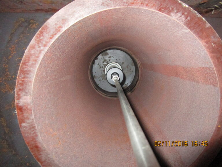
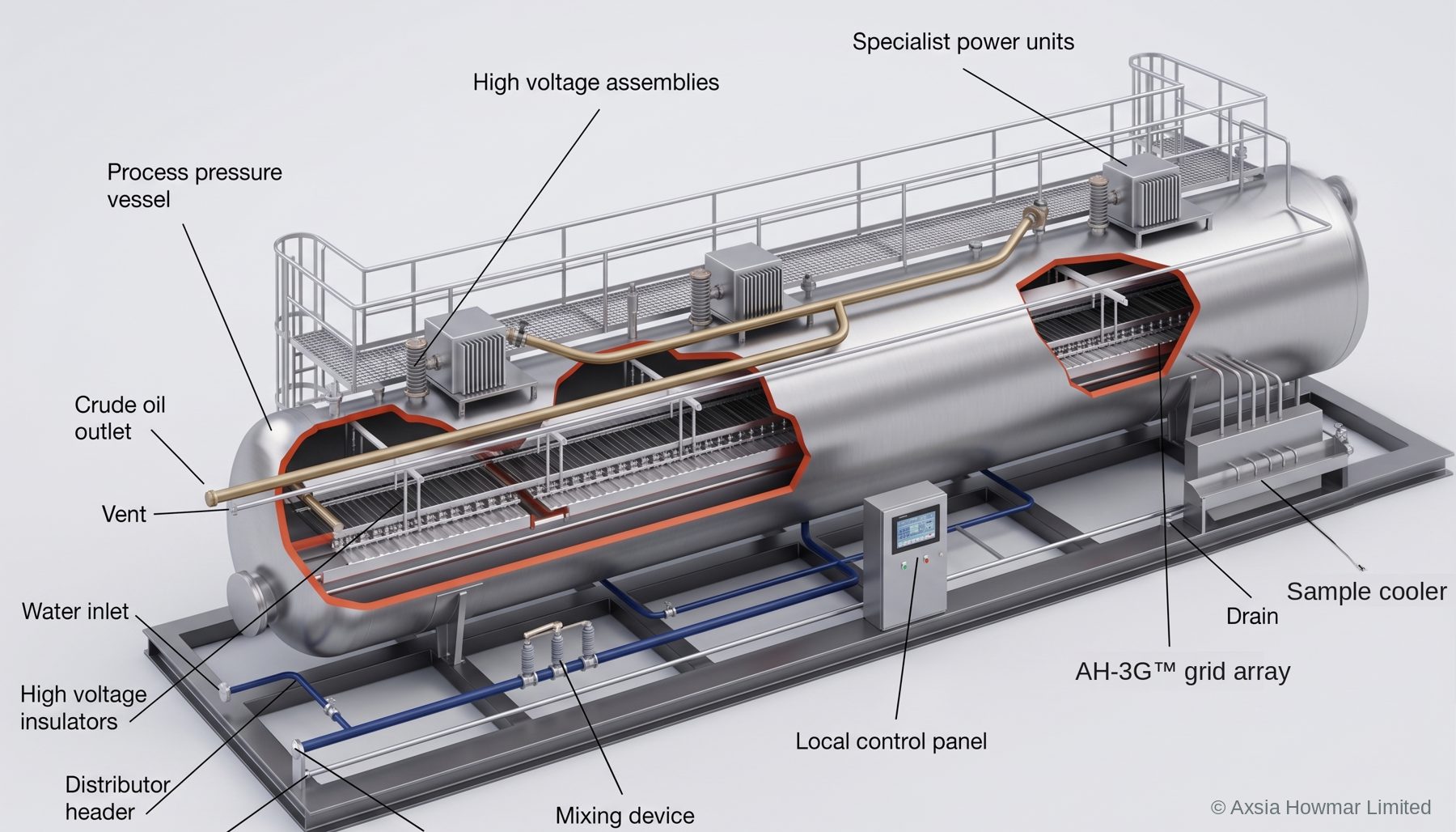
The dehydrator and the desalter are the same piece of equipment: a pressure vessel with electrode grids, fed by power units mounted on top, with a mixing device and wash water connection upstream for desalter duty.

See the components and internals

Cutaway model of a skid-mounted electrostatic desalter showing the pressure vessel, power units, high-voltage assemblies and insulators, electrode grid array, distributor header, mixing device and local control panel.

Why each stage of the crude oil treatment train exists

Each stage of a crude oil treatment train removes one obstacle to separating water from oil. Water settles out of crude at a rate described by Stokes’ law: settling velocity rises with the square of droplet diameter and with the density difference between water and oil, and falls as oil viscosity rises. Every stage in the train pulls one of those levers.

  • Separators remove gas and free water, so that the stages downstream deal only with emulsified water and are not disturbed by gas breakout.
  • Heaters lower viscosity. For most crudes they also widen the density difference, up to a temperature beyond which it narrows again.
  • Electrostatic coalescers increase droplet diameter, the most powerful lever because settling velocity depends on its square.
  • Wash water and the mixing valve do not help separation at all. They exist to dilute the brine, and they make the emulsion slightly harder to break. Desalting is always a balance between contact and separability.

How the stages of a crude oil treatment train interact

The stages of a crude oil treatment train interact, so a change in one shows up as a symptom in another. The diagram shows a typical arrangement. Select a number, or read the descriptions under it.

Crude oil treatment train: heater, dehydrator, wash water mixing and desalterFlow runs left to right. Wet crude with demulsifier passes through a heater, then a dehydrator. Wash water is added and mixed across a mixing valve, then the crude passes through a desalter and leaves as treated crude. Effluent water leaves the bottom of both vessels. Each vessel has a high-voltage power unit on top feeding electrode grids. Numbered points are described in the list below.Wet crude+ demulsifierHeaterHVDehydratorWash waterHVDesalterTreated crudeEffluent water to treatment12345
Simplified crude oil treatment train. Select a number, or read the descriptions below. Arrangement and number of stages vary with the crude and the product specification.
  1. Crude oil heaterThe heater raises the crude temperature so that oil viscosity falls and the emulsion weakens, which lets water droplets settle faster in the vessels downstream. Too little heat slows separation. Too much heat can vaporise light ends and increase fouling.
  2. DehydratorThe dehydrator is an electrostatic vessel that removes the bulk of the free and emulsified water, lowering basic sediment and water (BS&W) before the crude is desalted. Water leaves from the bottom of the vessel under interface level control.
  3. Wash water and mixing valveLow-salinity wash water is injected and sheared into the crude across the mixing valve so that it contacts and dilutes the remaining brine droplets. Mixing valve pressure drop sets droplet size: too little gives poor contact, too much creates an emulsion that is hard to break.
  4. DesalterThe desalter is a second electrostatic vessel. It coalesces the diluted brine droplets, which settle into the water phase and leave as effluent, carrying the salt with them. Outlet salt is usually expressed in pounds per thousand barrels (PTB).
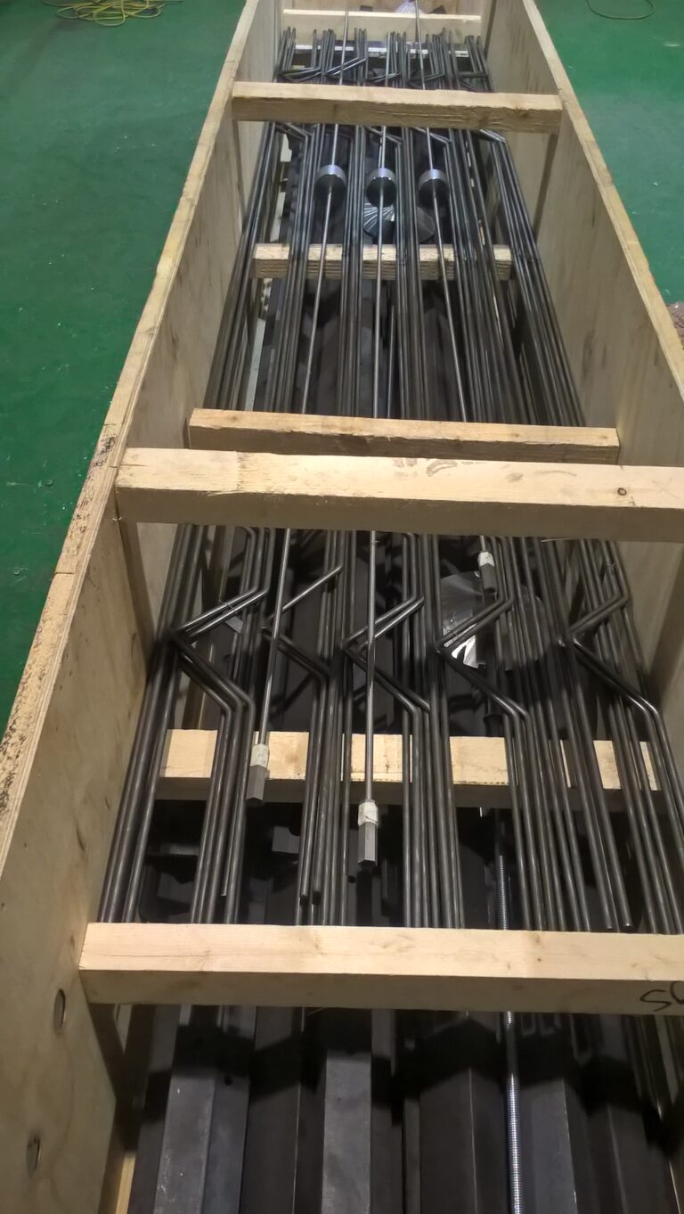
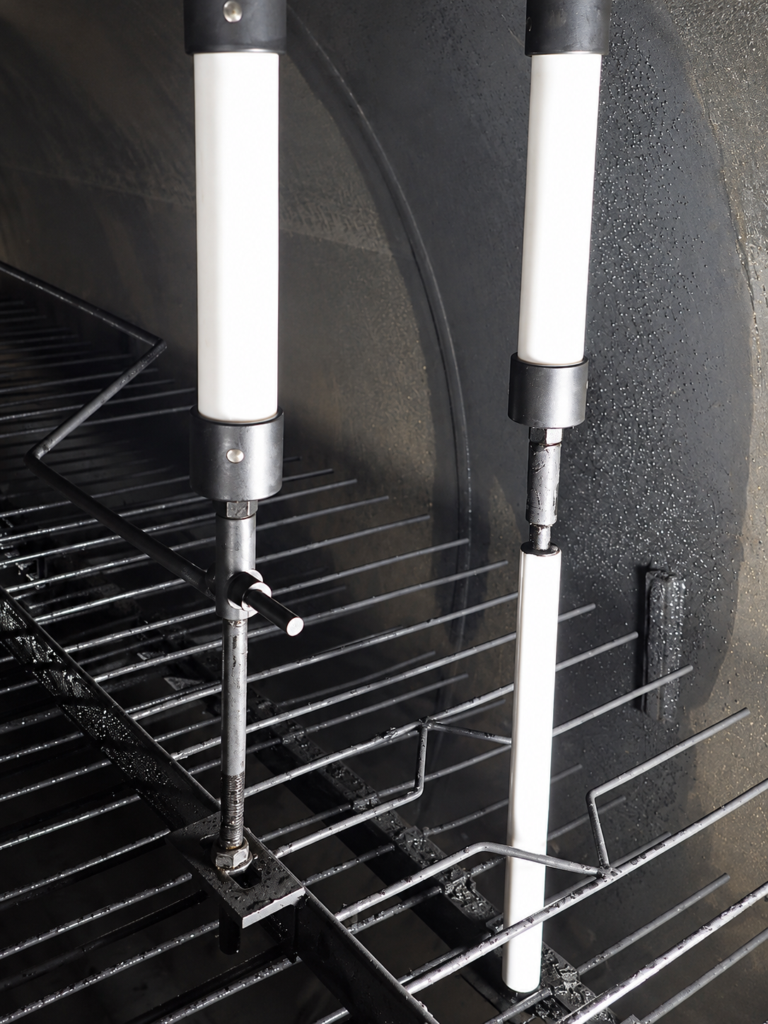
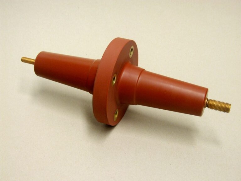
  5. Electrostatic grids and power unitA transformer supplies high voltage through an entrance bushing to electrode grids inside each vessel. The electric field polarises water droplets so that they collide and coalesce into drops large enough to settle by gravity. This is the electrostatic coalescer.

Three interactions explain most field behaviour:

  • Temperature and chemistry trade against each other. A train running colder than design needs more demulsifier to hold the same outlet basic sediment and water (BS&W), until no dose is enough.
  • Dehydration efficiency sets the limit on desalting. Outlet salt is roughly the water left in the crude multiplied by the salinity of that water. Wash water lowers the salinity; the coalescer lowers the water. Neither can compensate fully for the other.
  • The interface is shared. Solids, waxes and stabilised emulsion collect at the oil-water interface as a rag layer. If it grows towards the electrode grids, the electrical load rises and the power unit may trip, which stops coalescence and makes the rag layer grow faster.

Dehydrator, desalter and electrostatic coalescer: one vessel, three names

Dehydrator, desalter and electrostatic coalescer are names for the same equipment in different duties. The vessel, the electrode grids, the entrance bushing and the power unit are the same. A coalescer is called a dehydrator when it removes produced water, and a desalter when wash water is added upstream of it to dilute the salt. This site has one product page, electrostatic coalescers, and two duty pages that cover only what differs: dehydrator duty and desalter duty.

Design and selection considerations for a crude oil treatment train

The design of a crude oil treatment train starts from the crude and the specification, not from a standard package. The inputs that matter most are:

  • Crude density, reported as API gravity or kg/m³ at a stated temperature, and viscosity at two temperatures, so that viscosity at treating temperature can be calculated and not guessed.
  • Water cut now and over field life, produced water salinity, and inlet salt in PTB.
  • Emulsion stability from bottle tests on fresh samples, with and without demulsifier.
  • Solids, wax, asphaltene and naphthenic acid content, which drive rag layer growth and the need for mud washing.
  • The outlet specification for BS&W and salt, and the quality limit on effluent water.
  • Available heat, wash water quality and quantity, and hazardous area classification.

From these we fix the number of electrostatic stages, the treating temperature, the vessel size for the required residence time and grid loading, and the wash water and recycle philosophy.

Materials used in crude oil treatment equipment

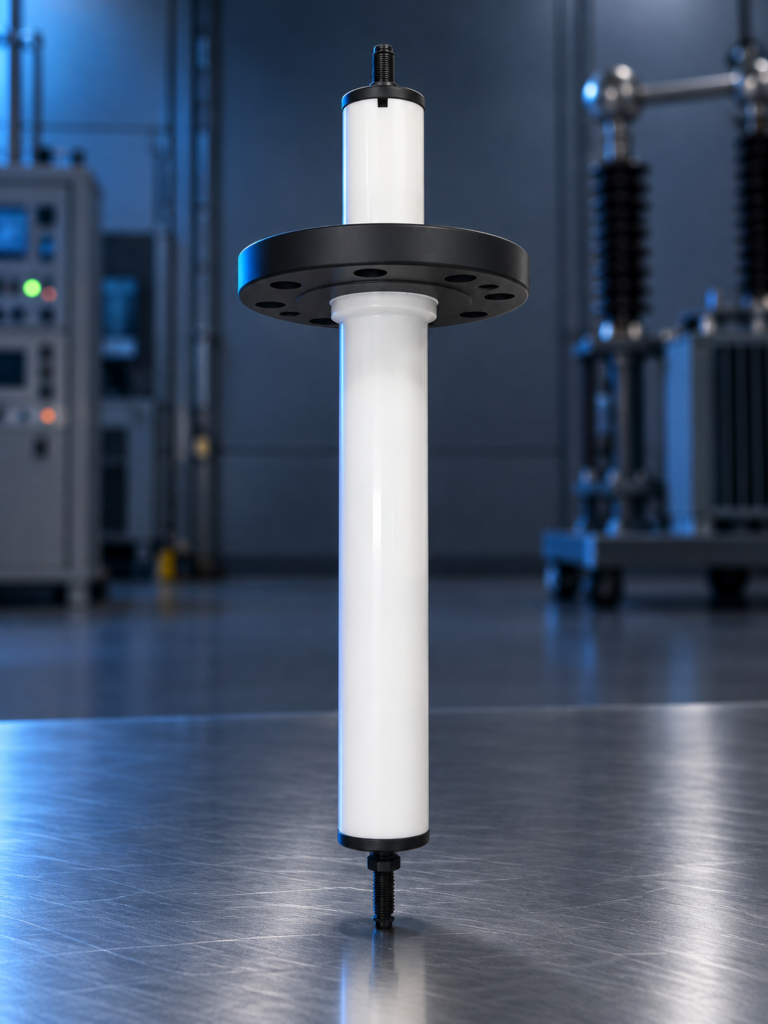
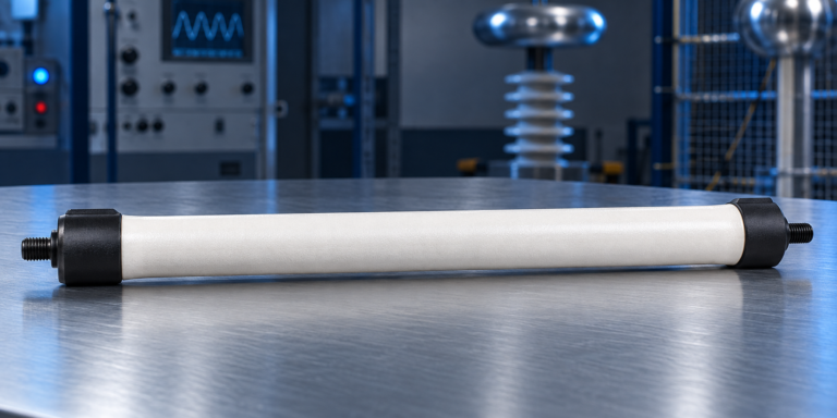
Crude oil treatment vessels are normally carbon steel with a corrosion allowance, internally coated or clad in the water phase where produced water chemistry requires it. Where hydrogen sulphide is present, wetted materials follow NACE MR0175 / ISO 15156. Electrode grids are steel; insulators, hangers and the entrance bushing use polytetrafluoroethylene (PTFE) or similar insulating materials chosen for the treating temperature.

Common operating problems in crude oil treatment, and where they originate

Operating problems in crude oil treatment usually appear at the outlet analyser but originate upstream. The most frequent are high BS&W or salt at the outlet, a power unit that trips or runs at low voltage, a growing emulsion band at the interface, and oily effluent water. Each has a short list of probable causes and a short list of data that separates them. The troubleshooting symptom index sets these out symptom by symptom.

Capacity enhancement and revamp options for crude oil treatment trains

A crude oil treatment train that has run out of capacity can often be re-rated without new vessels. Options, in rough order of cost, are: restoring design temperature; re-optimising mixing valve pressure drop, wash water rate and demulsifier; replacing worn or damaged grids, insulators and bushings; upgrading the grid arrangement or power units within the existing shell; improving inlet distribution; and adding a stage. A design review for capacity enhancement establishes which limit is actually binding before money is spent.
Design parameters: Crude oil treatment

Design parameters: Crude oil treatment
ParameterTypical rangeUnitBasis / note
Treating temperature, upstream40 to 90°CTypical published range; set by crude viscosity and emulsion stability
Treating temperature, refinery desalter90 to 150°CTypical published range; limited by vapour pressure at operating pressure
Wash water rate3 to 10vol% of crudeTypical published range, relative to dry crude rate
Mixing valve pressure drop0.3 to 1.5barTypical published range; differential pressure, so gauge or absolute is the same

Typical ranges for orientation only. The design basis for each unit is set from the feed analysis and the required product specification.

Codes and standards applied to Crude oil treatment

Typically applied; the governing codes are confirmed per project with the client and the jurisdiction.

ASME BPVC Section VIII Division 1
Pressure vessels Separator and coalescer vessels
PD 5500 / EN 13445
Unfired pressure vessels Where a UK or European code is specified
API 12L
Vertical and horizontal emulsion treaters Treater vessels where specified
API 560
Fired heaters for general refinery service Fired heaters where specified
IEC 60079 / ATEX / IECEx
Equipment for explosive atmospheres Transformers, junction boxes, instruments
NACE MR0175 / ISO 15156
Materials for sour service Wetted parts where hydrogen sulphide is present

Applications: Crude oil treatment

  • Oilfield production facilities: Treating produced crude to pipeline or export specification at a central processing facility or gathering station.
  • Refinery crude units: Desalting ahead of the crude distillation unit to limit corrosion, fouling and catalyst poisoning downstream.
  • Heavy and high-water-cut crudes: Trains with more heat, longer residence time or two electrostatic stages where one stage cannot reach specification.
  • Capacity increases: Re-rating or retrofitting existing trains when throughput or water cut has moved beyond the original design basis.

Scope of supply: Crude oil treatment

  • Process design of the complete train (Heat and material balance, stage count, temperatures, wash water and chemical philosophy)
  • Separators, heaters and electrostatic coalescer vessels with internals (Fabricated by an approved and audited fabricator under our supervision)
  • Transformers, power units, entrance bushings and electrode grids
  • Mixing valves, level and interface instruments, control panel
  • Skids, piping, inspection, testing and documentation
  • Delivery, commissioning, start-up support and operator training

Equipment and packages within Crude oil treatment

  • Crude oil dehydrators

    A crude oil dehydrator is an electrostatic coalescer used to remove produced water from crude so that it meets its basic sediment and water (BS&W) specification. It is the same equipment as…

  • Crude oil desalters

    A crude oil desalter removes salt from crude by mixing in low-salinity wash water to dilute the brine, then removing the water in an electrostatic coalescer. Salt leaves dissolved in the water.…

  • Crude oil heaters

    A crude oil heater raises crude to the temperature at which water can be separated from it. In oilfield treatment this is usually an indirect fired heater: a burner heats a liquid…

  • Electrostatic coalescer prewash

    An electrostatic coalescer prewash removes entrained caustic from kerosene after the caustic prewash of a kerosene sweetening unit. A high-voltage direct current (DC) field makes the fine caustic droplets merge and settle,…

  • Electrostatic coalescers

    An electrostatic coalescer is a pressure vessel that uses a high-voltage electric field to merge small water droplets in crude oil into drops large enough to settle by gravity. The same equipment…

Frequently asked questions: Crude oil treatment

What is the difference between crude oil dehydration and desalting?

Crude oil dehydration removes water from the crude. Crude oil desalting removes salt. Because the salt is dissolved in the water, desalting is dehydration with one extra step: fresh wash water is mixed in first to dilute the brine, so that the small amount of water left after coalescence carries less salt. Both duties use the same equipment, an electrostatic coalescer.

Why does crude oil need to be desalted before a refinery crude unit?

Salt in crude is mostly sodium, calcium and magnesium chloride dissolved in brine. In the crude unit heaters, calcium and magnesium chlorides hydrolyse to hydrogen chloride, which causes corrosion in the overhead system. Salts and solids also foul heat exchangers and heaters. Desalting upstream is cheaper than managing those effects downstream.

What BS&W and salt specification can a crude oil treatment train reach?

Common sales specifications are 0.5 or 0.2 vol% basic sediment and water and 10 pounds of salt per thousand barrels (PTB). Refinery desalters often target below 1 PTB. What a particular train can reach depends on the crude, the water cut, the temperature and the number of stages, so targets are set per project from the feed analysis.

When is a two-stage desalter needed instead of a single stage?

A second stage is needed when one stage of dilution and coalescence cannot bring the salt down to specification. That is usual for high inlet salt, heavy or viscous crudes, and refinery targets below about 1 PTB. In a two-stage arrangement the second-stage effluent water is normally recycled as first-stage wash water, which saves fresh water.

Where do most crude oil treatment problems start?

Most problems that show up at the outlet start upstream of it: a change in crude blend or water cut, a drop in treating temperature, demulsifier under-dosing or overdosing, mixing valve pressure drop set too high, or an interface level drifting towards the grids. That is why the train has to be diagnosed as one system.

Talk to an engineer about your unit

Tell us the equipment, the duty and what you are seeing. Partial data is normal: send what you have and we will tell you what else matters. We acknowledge every enquiry within 1 working day.