Crude oil treatment

Electrostatic coalescers

An electrostatic coalescer is a pressure vessel that uses a high-voltage electric field to merge small water droplets in crude oil into drops large enough to settle by gravity. The same equipment is called a dehydrator when it removes produced water and a desalter when wash water is added upstream. Axsia Howmar designs and manufactures both.

Typical field across the electrode grids
About 20 kV
Single-transformer design, or the AH-3G™ three-grid design, chosen by flow rate
1 or 3 grids
Power units that limit current and stay on line during upsets
100 % reactance

Send a technical enquiry

How it works: Electrostatic coalescers

  1. Emulsion enters through a distributor

    The inlet distributor spreads the emulsion along the vessel at low velocity, so that the whole electrode area is used and the interface is not disturbed.

  2. The field polarises the droplets

    Electrode grids, fed from a transformer through a high-pressure entrance bushing, create an electric field in the oil phase. Each conductive brine droplet becomes a dipole, and neighbouring droplets attract one another.

  3. Droplets collide and coalesce

    The field also stretches and moves droplets, which thins the surfactant film between them. Droplets merge, and drop diameter grows by an order of magnitude or more.

  4. Water settles to the interface

    Enlarged drops fall through the oil to the oil-water interface. Settling velocity rises with the square of drop diameter, which is why coalescence matters more than residence time alone.

  5. Oil and water leave separately

    Treated crude is collected along the top of the vessel. Water, with the salt dissolved in it, leaves from the bottom under interface level control.

Desalter components

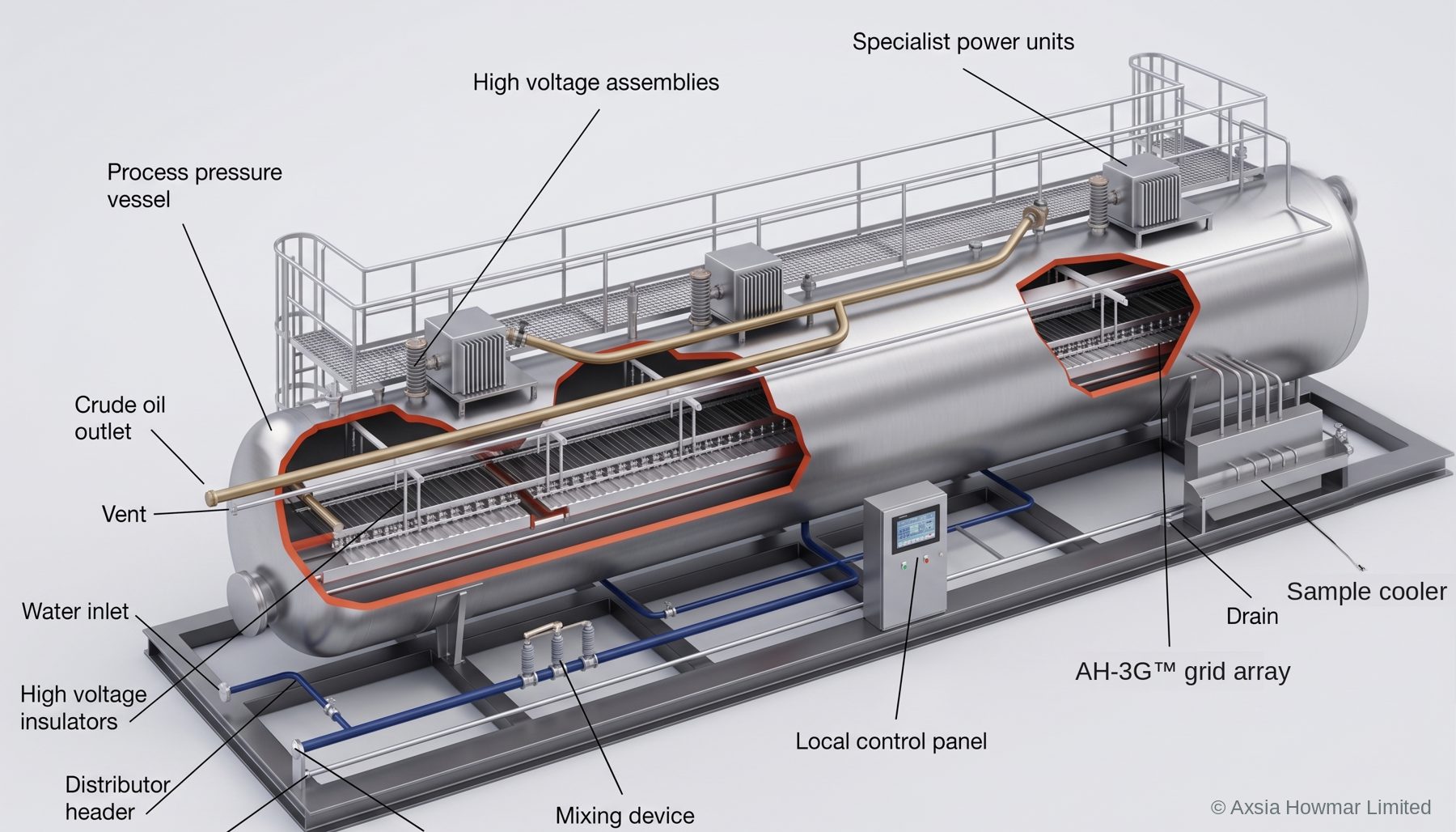
The components of an electrostatic desalter

Crude and wash water pass through the mixing device and enter the vessel through a distributor header below the electrode grids. The electrostatic field merges the water droplets, which fall through the oil carrying the salts and other impurities with them. The water is discharged continuously to the effluent system for further treatment, and clean, dry crude leaves from the top of the vessel for export or storage.

  • Process pressure vessel with crude inlet and outlet, vent and drain
  • Power units mounted on the vessel, one for each grid
  • High-voltage assemblies (entrance bushings) and high-voltage insulators
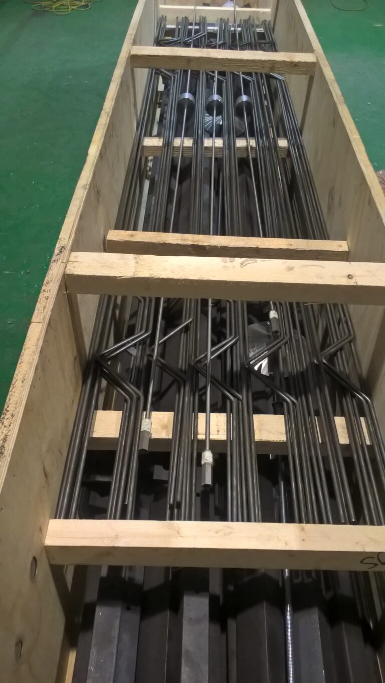
  • Electrode grid array
  • Distributor header, wash water inlet and effluent water outlet
  • Mixing device upstream of the vessel
  • Local control panel and sample cooler
Cutaway model of a skid-mounted electrostatic desalter with its main components labelled.

AH-3G™ three-grid internals

The AH-3G™ three-grid electrostatic coalescer

The efficiency of an electrostatic coalescer follows the intensity of the field inside the vessel; a field of about 20,000 volts is typical. For dry crude flow rates up to about 50,000 barrels per day, a single-transformer design, with its balanced electrical load, is often the right choice.

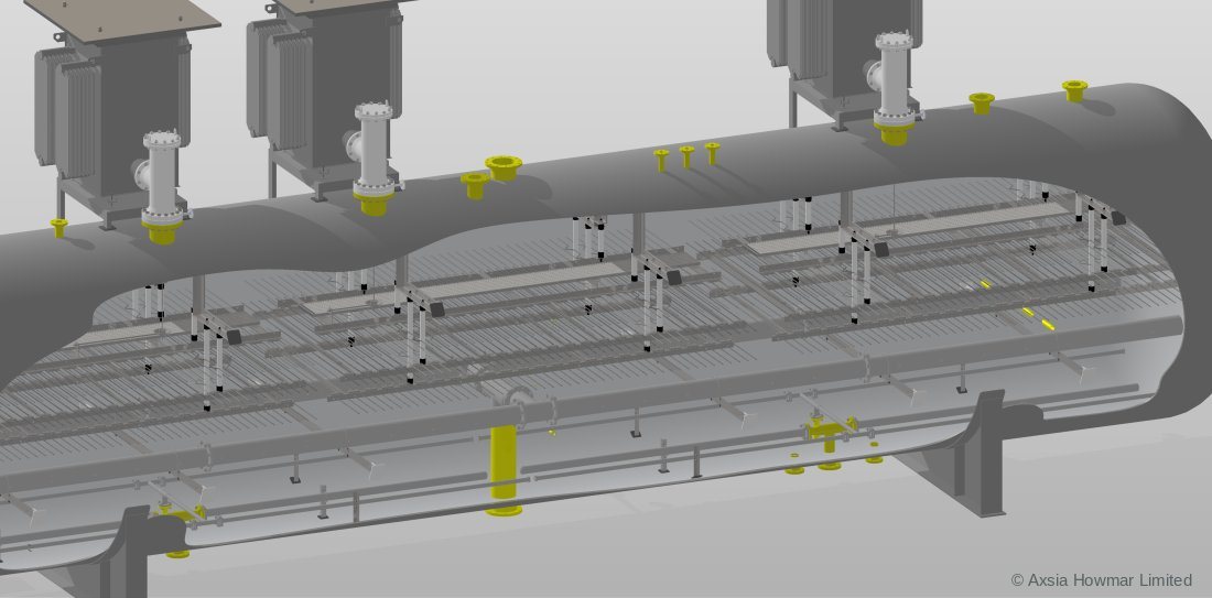
For higher flows the AH-3G™ three-grid design is usually selected. Three parallel horizontal electrode grids are hung inside the vessel on insulators, cross-connected, and each grid is supplied by its own power unit through its own entrance bushing.

The power units are a special-purpose design with 100 % reactance. They limit their own current when the grids see conductive emulsion, so they cannot be overloaded and the unit stays on line through upsets.

Section through a AH-3G™ three-grid coalescer: three power units and entrance bushings on the vessel, and the electrode grids hung on insulators above the distributor.

Where an electrostatic coalescer sits in the process

An electrostatic coalescer sits downstream of gas-liquid separation and heating, where the crude carries only emulsified water. In an oilfield train it is normally the last stage before storage or export. In a refinery it sits in the crude preheat train, upstream of the crude unit heater, at the temperature that gives the best balance of viscosity, water solubility and vapour pressure. The crude oil treatment overview shows the full train.

Inside an electrostatic coalescer vessel

The internals of an electrostatic coalescer are few, and each has one job. Select a number on the drawing, or read the descriptions under it.

Cutaway of a horizontal electrostatic desalter or dehydrator vesselSide view of a horizontal pressure vessel. A transformer on top feeds an entrance bushing that passes through the shell to electrode grids hung from insulators in the upper oil phase. An inlet distributor runs along the vessel below the grids. Water collects in the lower part below a controlled interface and leaves from a bottom outlet. Treated crude leaves through a collector at the top. Numbered points are described in the list below.Oil phaseWater phaseHVTreated crudeFeed inEffluent water12345678
Generic arrangement of a horizontal electrostatic desalter or dehydrator. Internals differ between designs; this drawing is not to scale.
  1. Transformer and power unitMounted on or beside the vessel, the power unit steps the supply up to the high voltage applied to the electrodes. Repeated tripping of the power unit usually points to a conductive path inside the vessel, such as a high interface, a wet emulsion layer or a failed insulator or bushing.
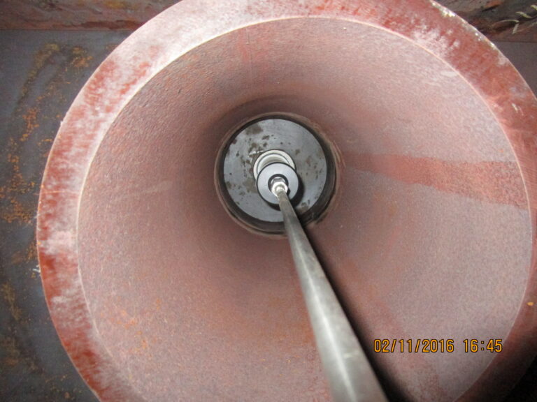
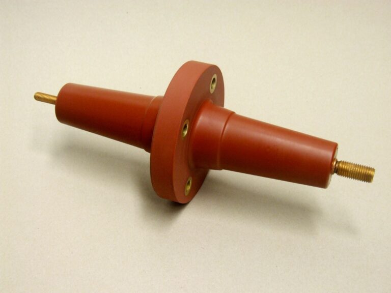
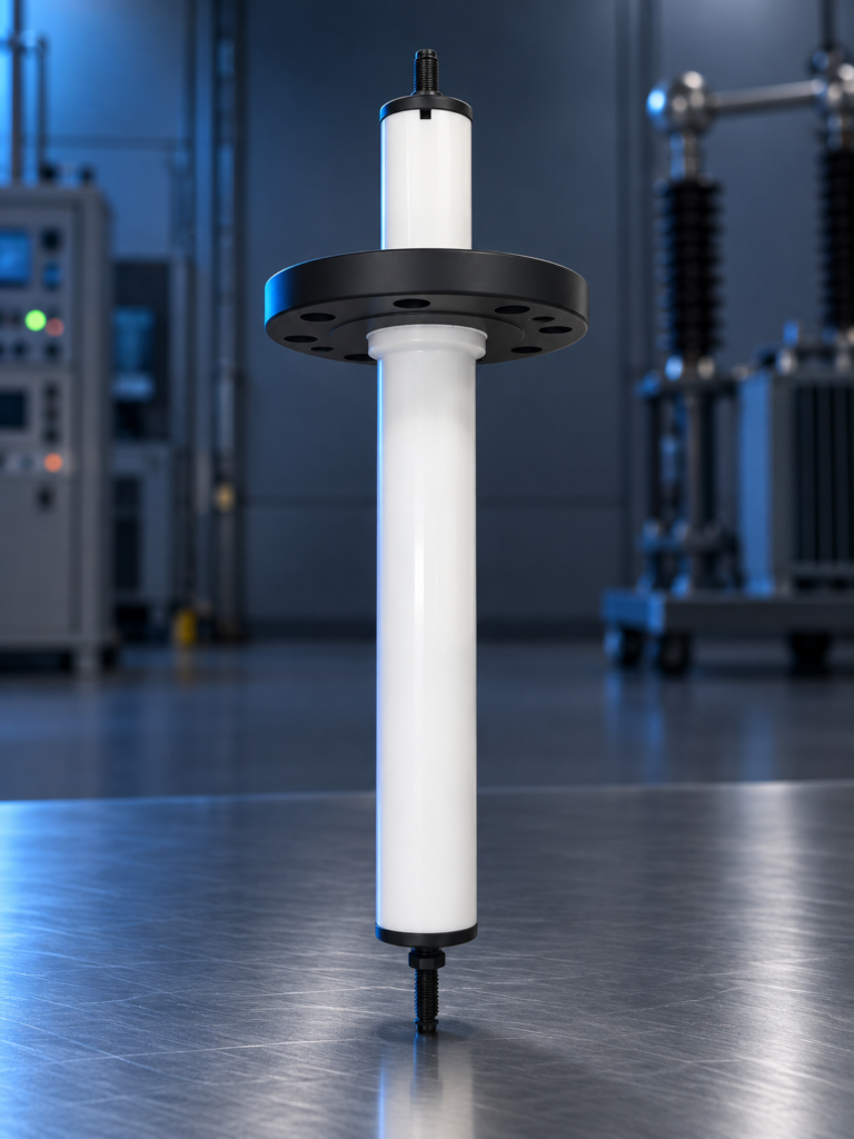
  2. High-pressure entrance bushingThe entrance bushing carries the high-voltage conductor through the pressure boundary into the vessel while insulating it from the shell. It is both a pressure part and an electrical insulator, and it is one of the most commonly replaced spare parts.
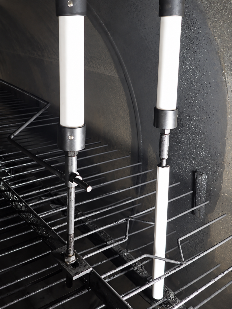
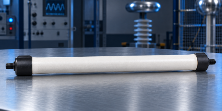
  3. Electrode insulators and hangersInsulators suspend the energised electrode grids from the vessel while keeping them electrically isolated from it. Surface contamination or cracking lets current track to earth and drags down the field voltage.
  4. Electrode gridsThe grid assembly creates the electric field between energised and earthed electrodes. Water droplets passing through the field are polarised, collide and coalesce. Grid spacing and voltage are matched to the crude and the water cut.
  5. Inlet distributorThe distributor spreads the incoming emulsion evenly along the vessel at low velocity so that the whole grid area is used. Its position relative to the interface depends on the vessel design.
  6. Oil-water interface and level measurementCoalesced water settles into the lower water phase. The interface level is measured and controlled: too high and conductive water approaches the grids; too low and oil leaves with the effluent water.
  7. Outlet collectorThe collector header gathers treated crude from the top of the vessel along its length, keeping upward velocity uniform so that droplets are not carried over.
  8. Effluent water outletWater and the salt dissolved in it leave from the bottom of the vessel under interface level control and go to water treatment.

Design and selection considerations for electrostatic coalescers

The design of an electrostatic coalescer is set by the crude, the water and the duty. The main choices are:

  • Field type. Alternating current (AC) fields tolerate high water cuts and are the most common. Designs that combine AC and direct current (DC) fields add electrophoretic movement of droplets and can treat to lower water contents.
  • Grid arrangement. The number of grid levels and their spacing set the field strength and the area available for treatment.
  • Vessel size. Diameter and length follow from grid loading, settling time at treating viscosity, and the water volume needed for stable interface control.
  • Inlet distribution. Poor distribution wastes grid area and disturbs the interface. It is a common limit in older vessels.
  • Interface measurement. The rag layer confuses simple level instruments. Technology is chosen for the emulsion and solids expected.
  • Solids handling. Where sediment is expected, a mud wash system keeps the vessel bottom clear without a shutdown.

Materials of construction for electrostatic coalescers

Electrostatic coalescer shells are normally carbon steel with a corrosion allowance, with internal coating or cladding in the water phase where brine chemistry requires it. Insulators, hangers and the entrance bushing use PTFE or comparable insulating materials rated for the treating temperature and pressure. Gaskets and seals are selected for aromatics content and temperature.

Common operating problems with electrostatic coalescers

The common operating problems with electrostatic coalescers are high water or salt at the outlet, low grid voltage or power unit trips, growth of the emulsion band at the interface, and oil carried under into the effluent water. Most trace to four causes: feed that has moved away from the design basis, low temperature, chemical dosing, or a failing electrical component. The troubleshooting symptom index lists probable causes and the data that confirms each.

Capacity enhancement and revamp options for electrostatic coalescers

An electrostatic coalescer can often treat more crude, or wetter crude, within its existing shell. Revamp options include replacing damaged or fouled grids, fitting new entrance bushings and insulators, upgrading power units, improving the inlet distributor and upgrading interface measurement. Our design review service identifies the binding limit first. Parts for existing units, including units built by others, are listed under electrostatic coalescer spare parts.
Design parameters: Electrostatic coalescers

Design parameters: Electrostatic coalescers
ParameterTypical rangeUnitBasis / note
Operating temperature40 to 150°CTypical published range across upstream and refinery duties
Operating pressureAbove crude vapour pressure at operating temperaturebargGauge pressure; margin set per project to prevent gas breakout
Electrode voltage, transformer secondary12 to 25kVTypical published range; alternating current (AC) designs

Typical ranges for orientation only. The design basis for each unit is set from the feed analysis and the required product specification.

Codes and standards applied to Electrostatic coalescers

Typically applied; the governing codes are confirmed per project with the client and the jurisdiction.

ASME BPVC Section VIII Division 1
Pressure vessels Shell, heads, nozzles
PD 5500 / EN 13445
Unfired pressure vessels Where a UK or European code is specified
API 12L
Emulsion treaters Where specified for oilfield treaters
IEC 60079 / ATEX / IECEx
Equipment for explosive atmospheres Transformer, junction boxes, level instruments
PED / UKCA / UKEX
Conformity marking Where the installation jurisdiction requires it
NACE MR0175 / ISO 15156
Sour service materials Wetted parts where hydrogen sulphide is present

Applications: Electrostatic coalescers

  • Dehydrator duty: Removing produced water from crude at production facilities to reach the BS&W specification.
  • Desalter duty: Removing salt from crude, at production facilities or ahead of a refinery crude unit, with wash water and a mixing valve upstream.
  • Electrostatic prewash: Removing caustic or water haze from kerosene and similar products, for example in kerosene sweetening units.

Scope of supply: Electrostatic coalescers

  • Process design and performance basis (From crude assay, water cut and specification)
  • Pressure vessel with inlet distributor, outlet collector, electrode grids, insulators and hangers (Fabricated by an approved and audited fabricator under our supervision)
  • Transformer or power unit, entrance bushing, high-voltage conductor and junction boxes
  • Interface level measurement and control; mud wash system where required
  • Mixing valve and wash water controls for desalter duty
  • Commissioning, start-up support and operator training

Frequently asked questions: Electrostatic coalescers

How does an electrostatic coalescer work?

An electrostatic coalescer applies a high-voltage field across crude oil that contains small water droplets. The water is conductive and the oil is not, so each droplet polarises and attracts its neighbours. Droplets collide, merge and grow until they are heavy enough to settle to the water phase at the bottom of the vessel.

Is a desalter the same as a dehydrator?

A desalter and a dehydrator are the same equipment, an electrostatic coalescer, used in different duties. In dehydrator duty the vessel removes produced water. In desalter duty, fresh wash water is first mixed into the crude to dilute the brine, and the vessel then removes that diluted water. The internals and power unit are the same.

What voltage does a desalter transformer operate at?

Desalter and dehydrator transformers typically deliver between about 12 and 25 kV on the secondary side in alternating current designs. They are usually built with high reactance so that current is limited when the grids see conductive emulsion, which protects the unit during upsets.

Why does the power unit on an electrostatic coalescer trip?

A power unit trips or runs at low voltage when there is a conductive path between the energised grids and earth. The usual causes are an interface level or emulsion band that has risen towards the grids, very wet feed, or a failed entrance bushing or insulator. The troubleshooting symptom index lists how to tell these apart.

How is an electrostatic coalescer sized?

An electrostatic coalescer is sized on the oil flow per unit of grid area, the residence time needed for drops to settle at treating temperature, and the water handling capacity of the lower section. Viscosity at treating temperature dominates the result, which is why two viscosity measurements at different temperatures are requested at the start.

Can an existing desalter be upgraded without replacing the vessel?

An existing desalter can often be upgraded within its shell. Options include new electrode grids, higher-capacity power units, a better inlet distributor, upgraded interface measurement and a mud wash system. Whether that is enough depends on which limit is binding, which a design review establishes first.

Talk to an engineer about your unit

Tell us the equipment, the duty and what you are seeing. Partial data is normal: send what you have and we will tell you what else matters. We acknowledge every enquiry within 1 working day.