Upstream crude oil treatment

Crude oil degasser dehydrator

A crude oil degasser dehydrator is a two-vessel package: a degasser stacked above an electrostatic dehydrator on one skid. The crude flashes in the upper vessel and the released gas leaves to the vent or low-pressure gas system; the de-gassed liquid flows by hydrostatic head into the liquid-full dehydrator below, where the electrostatic field removes the emulsified water. The arrangement keeps gas away from the electrode grids, needs no transfer pump, and takes the plot of a single vessel. Axsia Howmar designs and manufactures the package and offers performance surveillance for dehydrators and desalters of any make: the signals the control system already has, read daily against the design model by the engineers who design the equipment.

Degasser stacked above the electrostatic dehydrator, lifted in as one piece
Two vessels, one skid
Dehydrator held liquid-full above the flash pressure; the field sees liquid only
No gas at the grids
Hydrostatic head from the upper vessel moves the crude down into the dehydrator
No transfer pump

Send a technical enquiry Performance surveillance

How it works: Crude oil degasser dehydrator

  1. Flash in the degasser

    Crude from the separator or heater enters the upper vessel and flashes at the package pressure. Gas leaves from the top; liquid collects in the bottom.

  2. Down to the dehydrator by head

    The height of the degasser drives the de-gassed liquid through a down-comer into the lower vessel, which runs liquid-full a little above the flash pressure so no more gas breaks out.

  3. Coalesce under the grids

    The liquid enters through the distributor beneath the electrode grids. The field merges the emulsified water droplets until they are heavy enough to settle.

  4. Water out, dry crude out

    Water leaves from the bottom under interface control; dry crude leaves from the top of the liquid-full dehydrator to storage or export.

The package

Degasser above, dehydrator below: one skid, one hydrostatic path

The crude enters the upper vessel and flashes at the package pressure. Gas leaves from the top to the vent or low-pressure gas system; the de-gassed liquid collects in the bottom and flows by its own head down the down-comer into the dehydrator, which runs liquid-full a little above the flash pressure so that no further gas can break out around the electrode grids.

Both vessels, the power units on their platform, the down-comer and interconnecting piping, the inlet distributor, the level and interface instruments and the local control panel sit on one skid. The package is lifted in as one piece, is piped up at four nozzles, and takes the plot of a single horizontal vessel. No transfer pump is needed between the two stages.

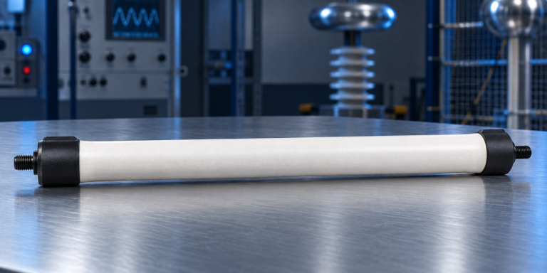
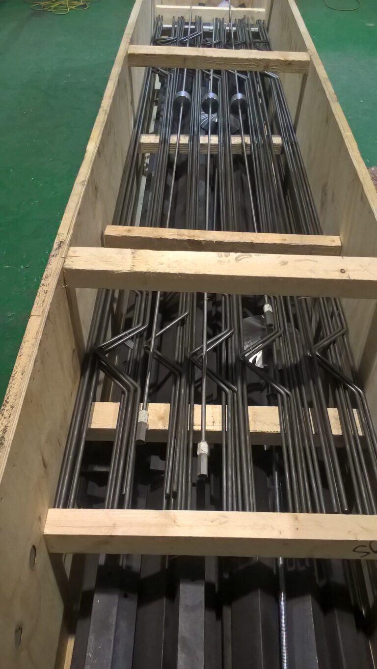
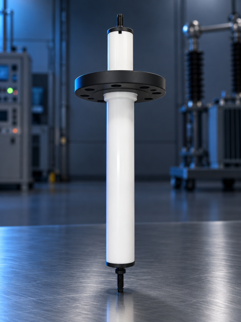
Inside the dehydrator: grids, insulators and power units

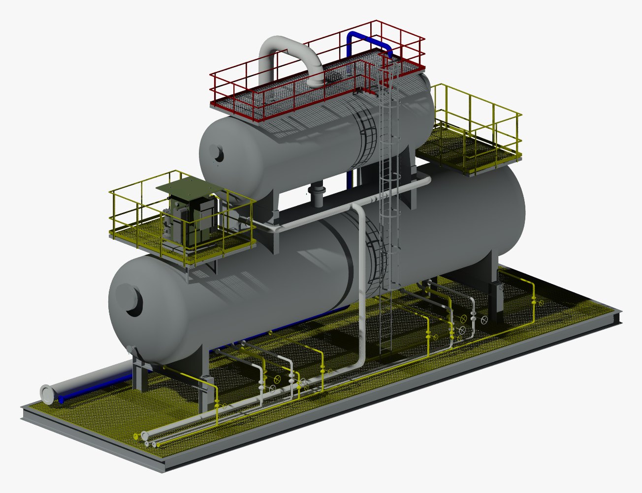
3D model of a crude oil degasser dehydrator package: the degasser with its platform above, the electrostatic dehydrator with its power unit platform below, down-comer, skid piping, ladders and access platforms on one frame.

Why the gas comes out first

An electrostatic field works on liquid, not on foam

Crude from a low-pressure separator, or crude that has just been heated, still carries dissolved gas. If it is given no other chance, that gas comes out of solution inside the dehydrator: bubbles rise through the grid zone and disturb the field, carry water droplets back up with them, and collect as a gas pocket under the top of a vessel that was designed to run liquid-full.

  • An unsteady interface, because the oil outlet level moves as the gas pocket grows and shrinks
  • Power units that hunt or trip, because gas and lifted water make the field load uneven
  • A BS&W reading that will not settle, because droplets that had started to settle are lifted back into the oil
  • All three gone when the gas is taken off in a degasser ahead of the field

Symptom index for dehydrators and desalters

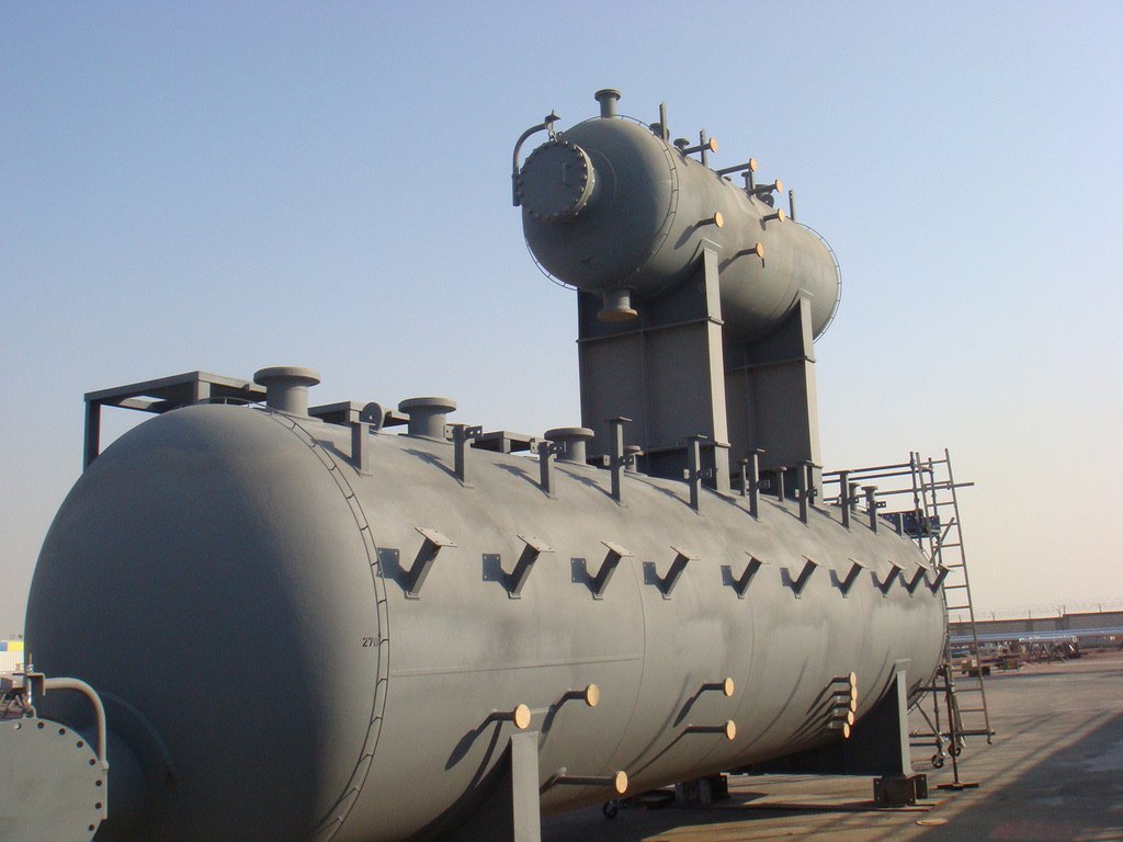
Degasser dehydrator vessels in the fabricator's yard before painting is complete: the degasser mounted above the dehydrator on its support frame, nozzles and manways flanged off for transport.

Performance surveillance

The fault shows in the data before it shows in the crude

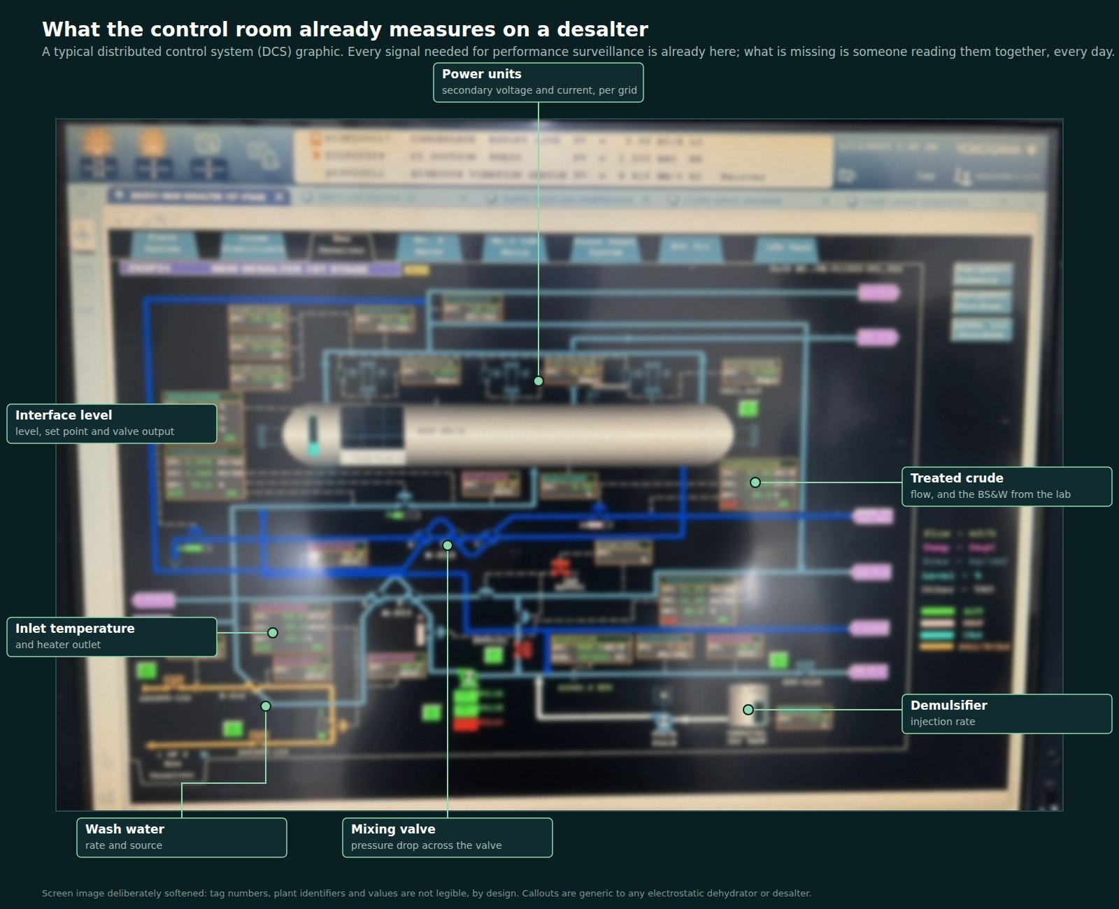
The signals that say how a dehydrator is really running are already on the control system: interface level, power unit secondary voltage and current, inlet temperature, mixing valve pressure drop, wash water and demulsifier rates, treated crude flow, and the laboratory BS&W and salt. Axsia Howmar reads them every day against the design model of the vessel and returns a green, amber or red note with the cause and the action, for this package and for dehydrators and desalters of any make.

In a published case from a heavy-oil desalter, that kind of review picked a voltage imbalance out of the power unit data within a week and traced it to an over-tightened internal connector, replaced on a planned visit for the price of a small part while the crude had been on specification throughout.
Performance surveillance for dehydrators and desalters

A typical desalter graphic on a distributed control system, with the signals surveillance reads called out. The screen image is deliberately softened so that no tag number, plant identifier or value is legible.

Scope

What Axsia Howmar supplies

  • Process design

    Flash calculation, vessel sizing, hydrostatic head and residence time from the crude assay and the inlet conditions.

  • Two vessels, one skid

    Degasser, dehydrator, down-comer, distributor, grids, insulators and hangers; fabricated by approved and audited fabricators under our supervision.

  • Power units and bushings

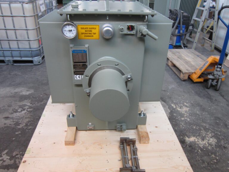
    Hazardous-area power units on their platform, entrance bushings, conductors and junction boxes.

  • Commissioning and after

    Start-up support, operator training, spare parts and performance surveillance once the unit is running.

In depth

Why the gas has to come out before the field goes on

An electrostatic dehydrator works on liquid. Its electrode grids hang in a vessel that is meant to run liquid-full, with the field applied across crude that carries emulsified water and nothing else. Crude that arrives from a low-pressure separator, or that has just been heated, is rarely in that state: lowering the pressure and raising the temperature both release dissolved gas, and that gas comes out of solution inside the dehydrator if it is given no other chance. Bubbles rising through the grid zone disturb the field, carry water droplets back up with them, and collect as a gas pocket under the top of the shell that the vessel was never designed to hold. The usual symptoms are an unsteady interface, power units that hunt or trip, and a basic sediment and water (BS&W) figure that will not settle.

The degasser dehydrator removes that gas first. The upper vessel is a degasser: the crude enters it, flashes at the package operating pressure, and the released gas leaves from the top to the vent or low-pressure gas system. The de-gassed liquid then passes down into the dehydrator below it, enters through the distributor beneath the electrode grids and is treated as in any electrostatic coalescer: the field merges the water droplets, the water settles to the bottom and leaves under interface control, and dry crude leaves from the top of the liquid-full vessel.

Why the two vessels are stacked

Stacking the degasser above the dehydrator is not only a matter of plot area. The height of the upper vessel gives a hydrostatic head that drives the liquid into the lower vessel through a down-comer without a pump, and keeps the dehydrator liquid-full at a pressure a little above the flash pressure in the degasser, so that no further gas can break out around the grids. One skid carries both vessels, the power units on their platform, the down-comer and interconnecting piping, the inlet distributor, the level and interface instruments, and the local control panel. The package arrives as one lift, is piped up at four nozzles, and takes the plot of a single horizontal vessel.

The dehydrator itself is the same electrostatic coalescer that Axsia Howmar supplies as a stand-alone vessel, with the same grids, insulators, entrance bushings and power units, so the spare parts and the service support are the same. Where the crude also needs desalting, wash water injection and a mixing valve are added ahead of the degasser and the package runs in desalter duty.

Performance surveillance: catch the fault while the crude is still on specification

The signals that tell you how a dehydrator is really running are already in the control room: interface level, the secondary voltage and current of each power unit, inlet temperature, the pressure drop across the mixing valve, wash water and demulsifier rates, treated crude flow, and the daily laboratory BS&W and salt. What is usually missing is anyone reading them together, every day, against what the vessel was designed to do. Operations staff watch the alarms; the slow drifts that come before a failure never reach an alarm limit, and the treated crude is the last thing to show them.

Axsia Howmar offers performance surveillance for this package and for dehydrators and desalters of any make: a daily export from the plant historian, read by the engineers who design the equipment against the design model of the vessel, and returned as a green, amber or red note with the cause and the action. In a published case from a heavy-oil desalter, that kind of review picked a voltage imbalance out of the power unit data within a week and traced it to an over-tightened internal connector, replaced on a planned visit for the price of a small part while the crude had been on specification throughout.
Design basis

Typical design parameters

Design parameters: Crude oil degasser dehydrator
ParameterTypical rangeUnitBasis / note
Operating temperature40 to 90°CTypical for upstream dehydration; set by the crude viscosity and the emulsion
Operating pressureSet by the flash pressurebargGauge pressure; low, typically a few barg, with the dehydrator held slightly above the degasser
Electrode voltage, transformer secondary12 to 25kVTypical published range; alternating current (AC) designs
Gas off the degasserTo vent, flare or low-pressure gasRate from the flash calculation on the crude and the inlet conditions
Inlet water cutEmulsified water only% volFree water is removed upstream; the dehydrator is sized for the emulsified remainder

Typical ranges for orientation only. The design basis for each unit is set from the feed analysis and the required product specification.

Design targets

Performance we design to

Performance we design to: Crude oil degasser dehydrator
MetricValue or rangeUnitConditions / design basis
Treated crude BS&W0.1 to 0.5% volTypical specification range; set per project by the export or sales specification
Gas carried into the dehydratorNone by designDehydrator held liquid-full above the flash pressure of the degasser

Achievable performance depends on feed conditions and the agreed design basis. These figures are design targets, not guarantees independent of those conditions.

Compliance

Codes and standards

Typically applied; the governing codes are confirmed per project with the client and the jurisdiction.

ASME BPVC Section VIII Division 1
Pressure vessels Both vessels, down-comer and nozzles
PD 5500 / EN 13445
Unfired pressure vessels Where a UK or European code is specified
API 12L
Emulsion treaters Where specified for oilfield treaters
IEC 60079 / ATEX / IECEx
Equipment for explosive atmospheres Power units, junction boxes, level instruments
NACE MR0175 / ISO 15156
Sour service materials Wetted parts where hydrogen sulphide is present

Applications

Where it is used

  • Crude from low-pressure separation

    Where the last separator runs close to the dehydrator pressure and the crude still carries dissolved gas that would break out around the grids.

  • Heated crude

    Where a heater ahead of the dehydrator releases gas from the crude; the degasser takes it before the field.

  • Tight plots and brownfield additions

    One skid on the footprint of a single horizontal vessel, lifted in as one piece and piped at four nozzles.

  • Dehydrator and desalter duty

    With wash water injection and a mixing valve ahead of the degasser, the same package desalts the crude.

  • Units of any make in service

    Performance surveillance and troubleshooting for degasser dehydrators, dehydrators and desalters built by others.

Scope of supply

What Axsia Howmar supplies

  • Process design: flash calculation, vessel sizing, hydrostatic head and residence time from the crude assay and the inlet conditions
  • Degasser and dehydrator vessels, down-comer, distributor, electrode grids, insulators and hangersFabricated by an approved and audited fabricator under our supervision
  • Power units on their platform, entrance bushings, high-voltage conductors and junction boxes
  • Skid, platforms, ladders, interconnecting piping, level and interface instruments and local control panel
  • Commissioning, start-up support and operator training
  • Performance surveillance after start-up, for this package or for units of any makeoptional

Questions engineers ask

Frequently asked questions

Why not simply run the dehydrator at a higher pressure?

Raising the dehydrator pressure keeps the gas in solution, but it also raises the design pressure of a large vessel and of everything downstream, and it only works if the upstream pressure is available. A degasser lets the crude flash at the lowest practical pressure, takes the gas to the low-pressure gas system where it has value, and holds the dehydrator only slightly above that pressure. The stacked arrangement does it with hydrostatic head, so there is no transfer pump between the two vessels.

What goes wrong when gas reaches the electrode grids?

Gas bubbles rising through the grid zone disturb the field and carry water droplets upward with them, so droplets that had started to settle are lifted back into the oil. A gas pocket collects under the top of the shell and the vessel is no longer liquid-full, which moves the oil outlet level and upsets interface control. The usual signs are an unsteady interface, power units that hunt or trip, and a BS&W reading that will not settle. See the troubleshooting service for the symptom index.

What is performance surveillance, and what does it need from us?

A daily export or a read-only link from the plant historian of eight signals: interface level and controller output, power unit secondary voltage and current, inlet temperature, mixing valve pressure drop, wash water and demulsifier rates, treated crude flow, and the daily laboratory BS&W and salt. Axsia Howmar engineers check them against the design model of the vessel, against each other and against their own trend, and return a green, amber or red note with the cause and the action. No new instruments are needed on the vessel, and the service works for dehydrators and desalters of any make.

Can surveillance really find a fault before the product goes off specification?

Yes, because most faults in an electrostatic treater show in the power unit signals long before they show in the crude. In a published case from a heavy-oil desalter, a voltage imbalance between units was picked out of the streaming data within a week and traced to an over-tightened internal connector; it was replaced on a planned visit for the price of a small part, with no loss of production, while the treated crude had been on specification throughout. The surveillance service is a review of the signals, not a guarantee of performance: it tells you what the data shows and what to do about it.
Does Axsia Howmar fabricate the vessels?

Axsia Howmar designs and manufactures the package. Fabrication is subcontracted to approved and audited fabricators under our supervision, with the material certificates, pressure tests and inspection records supplied with the equipment.

Talk to an engineer about your unit

Tell us the equipment, the duty and what you are seeing. Partial data is normal: send what you have and we will tell you what else matters. We acknowledge every enquiry within 1 working day.