In depth
What the power unit does
The electrode grids in a desalter or dehydrator do nothing without a high-voltage supply. The desalter power unit is the transformer that provides it. It takes the plant supply, single-phase or three-phase at plant voltage, and steps it up to the grid voltage, an alternating current output typically between 14 and 22 kV selected on the tap changer according to the grid design and the crude. It is mounted on or beside the vessel, in the hazardous area, and its output is connected to the grid through the transformer bushing, the bushing housing and the entrance bushing on the vessel.
The load is unlike that of an ordinary transformer. The emulsion between the grids is mostly oil, which is a poor conductor, but its conductivity rises sharply with water content, temperature and salinity. When a wet slug arrives or the interface rises towards the grids, the emulsion conducts and the grids are, for a moment, almost short-circuited. A desalter transformer is therefore built with very high reactance, 100 % in the designs Axsia Howmar supplies, so that the current is limited to about its rated value, the voltage folds back, the slug passes and the field recovers. Without this the unit would trip on every upset, and a tripped field means wet crude leaving the vessel.
Configurations
Desalter and dehydrator power units are alternating current units. Two configurations cover the grid designs in use; the designations are those of the manufacturer, Betra, whose power units Axsia Howmar supplies for new vessels and as replacements.
- EOX: single-phase supply, one AC output. The standard unit for a single-grid vessel or for each grid of a three-grid vessel.
- EOXS: three-phase supply with two single-phase AC outputs from a Scott-connected transformer, which balances the load across the three phases of the supply and feeds two grids from one tank.
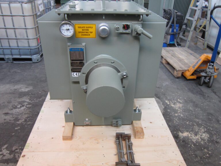
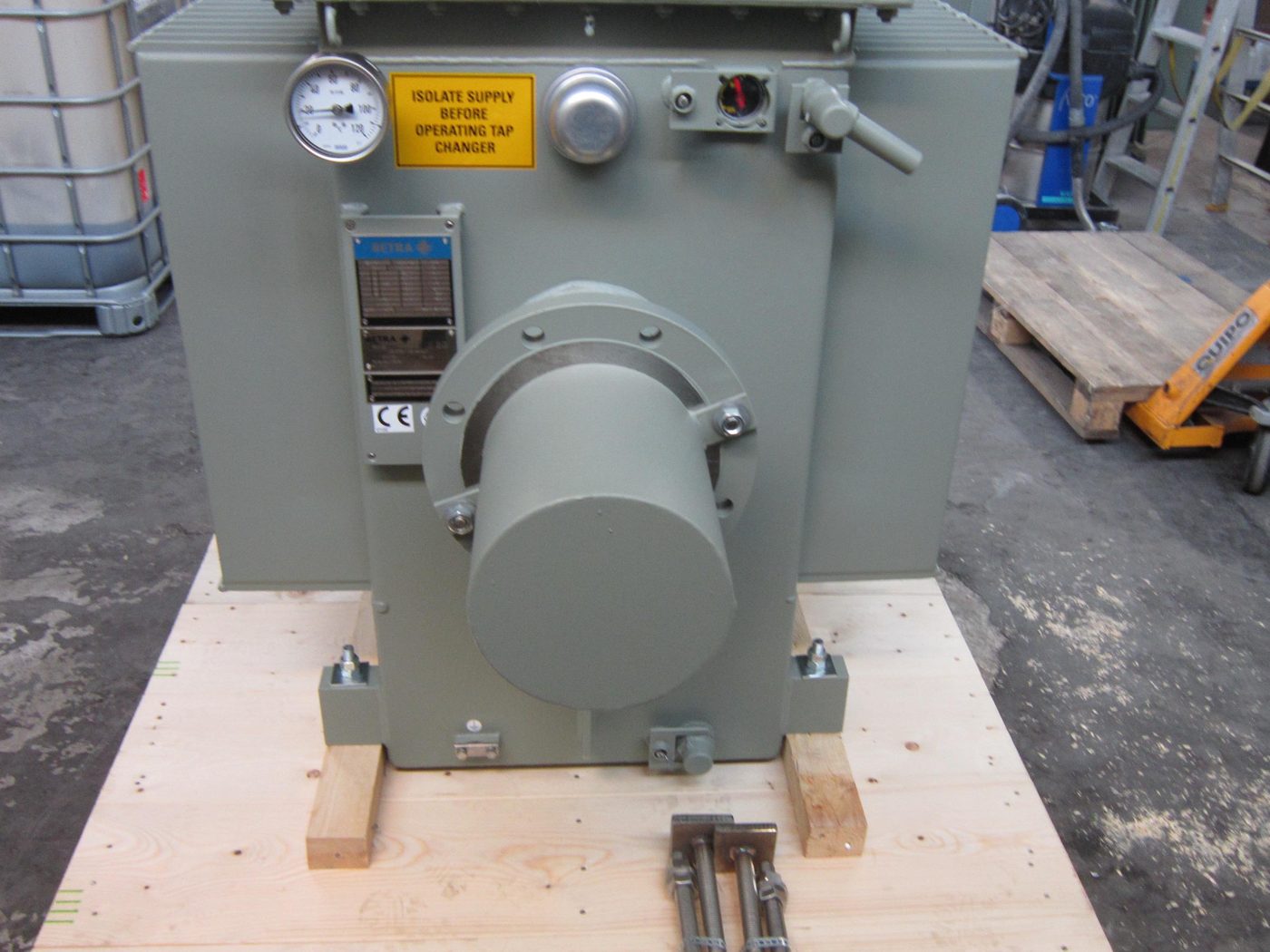
The output voltage is selected on an off-load tap changer. The typical tap positions are 14, 16, 18, 20 and 22 kV; other voltages, and units outside the usual rating range, are made to order. Every unit is built to the vessel it serves: the rating in kVA from the grid area and the crude, the tap voltages from the grid spacing, the supply voltage and frequency from the plant, and the mounting, the bushing housing and the transformer bushing from the vessel drawings. The supply is isolated before the tap changer is operated, and the warning plate on the tank says so. The unit is listed as a spare part, desalter power unit, for replacement on vessels of any make.
Construction
The transformer and its reactor sit in a welded steel tank filled with insulating oil. The oil both insulates the windings and carries their heat to the tank wall and the cooling fins, so the unit needs no fan and no external cooler. The tank is rated for the hazardous area around a desalter, in the designs supplied marked Ex eb ob II T5 Gb for Zone 1, that is increased safety and oil immersion protection with a surface temperature class of T5. On the tank are the oil temperature gauge, the oil level indicator, the breather or pressure relief device, the off-load tap changer with its warning plate, the earthing point and the nameplate, and on one face the flanged bushing housing that takes the output to the vessel. The units are rated for ambient temperatures from -55 to +60 °C, which covers desert, arctic and offshore installations including floating production, storage and offloading (FPSO) vessels.
The bushing housing: how the high voltage reaches the grid
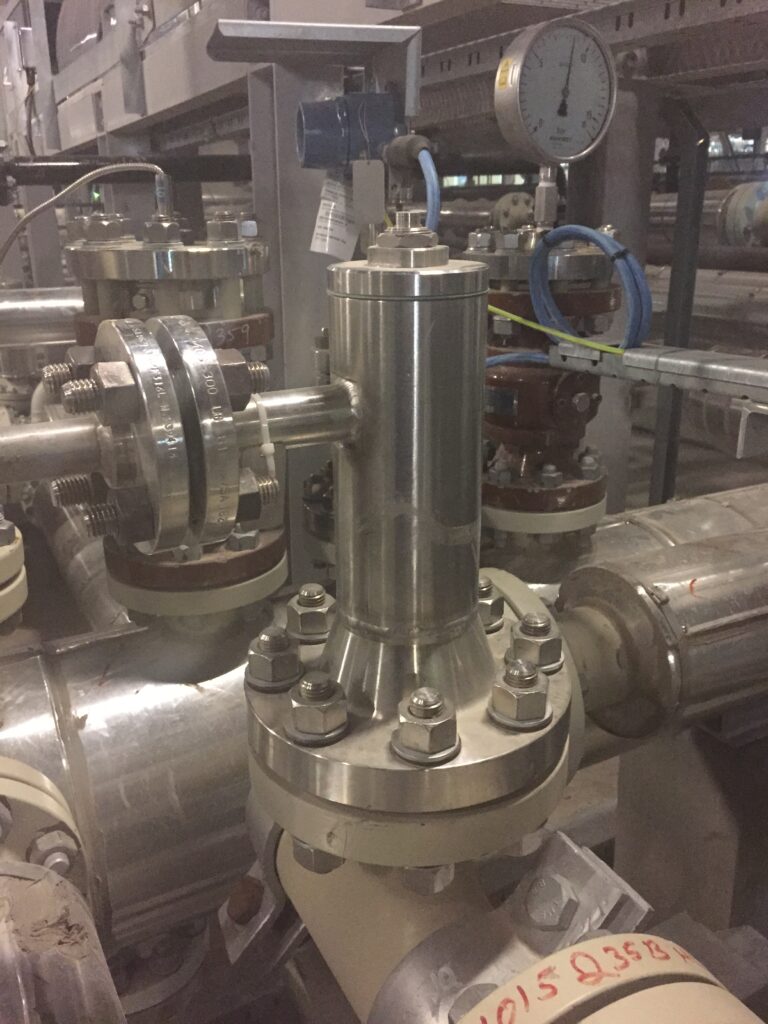
Between the transformer and the vessel is the part that most often decides whether a desalter runs or trips: the connection that carries tens of kilovolts from a tank full of oil into a vessel full of crude. On the units Axsia Howmar supplies it is made as a bushing housing, a tee-shaped spool piece, bolted to the transformer tank on one side and to the entrance bushing flange on the vessel below, and filled with insulating oil.
The high-voltage conductor leaves the transformer through a transformer bushing into the horizontal leg of the tee. Inside the housing it is connected to the top of the entrance bushing, which passes down through the vertical leg, across the vessel wall and into the process, where a connecting rod takes the current to the grid. The oil in the housing does three things. It insulates the live connection from the earthed steel of the housing, so that no part of the conductor is exposed to the atmosphere of the hazardous area. It excludes air and moisture from the connection, which is where surface tracking and flashover would otherwise begin. And it allows the housing to be compact: the clearances needed in oil are a fraction of those needed in air at the same voltage.
The tee form gives a third leg, closed with a blind flange, through which the connection is made up and inspected without dismantling the transformer or the entrance bushing. The housing has its own oil fill, drain and level connections. On a three-grid vessel each of the three power units has its own housing and entrance bushing; on a single-grid vessel there is one. When an entrance bushing is replaced, the housing is drained, the connection is broken at the tee, and the bushing is lifted out through the vessel nozzle; the transformer stays in place.
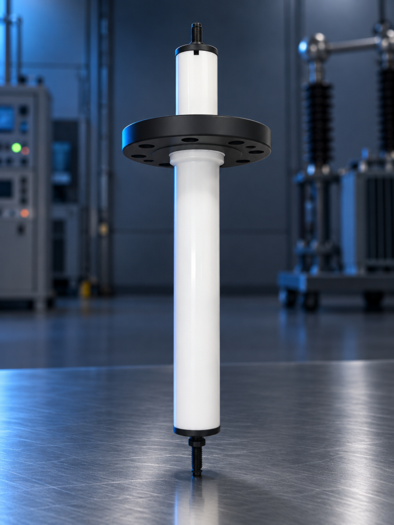
The entrance bushing itself, the transformer bushing and the insulators inside the vessel are described with the other electrostatic coalescer spare parts. A failed bushing, tracking on a wet or dirty housing, and low oil level in the housing are among the first things to check when a power unit trips; see the troubleshooting symptom index.
Specifying a replacement power unit
A replacement power unit for a vessel of any make is specified from the nameplate of the existing unit, the vessel general arrangement drawing and the entrance bushing drawing. The nameplate gives the rating, the supply and output voltages, the tappings and the hazardous-area marking; the drawings give the mounting, the bushing housing dimensions and the entrance bushing flange. Where the grid design is being changed in a revamp, the rating is recalculated from the new grid area and the crude. Send the nameplate photo and the drawings through the request a quote form, and quote the vessel tag number; power units are made to order.