Spare parts: transformers and power units

Desalter power unit

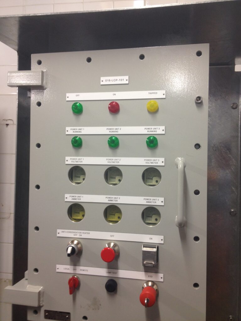
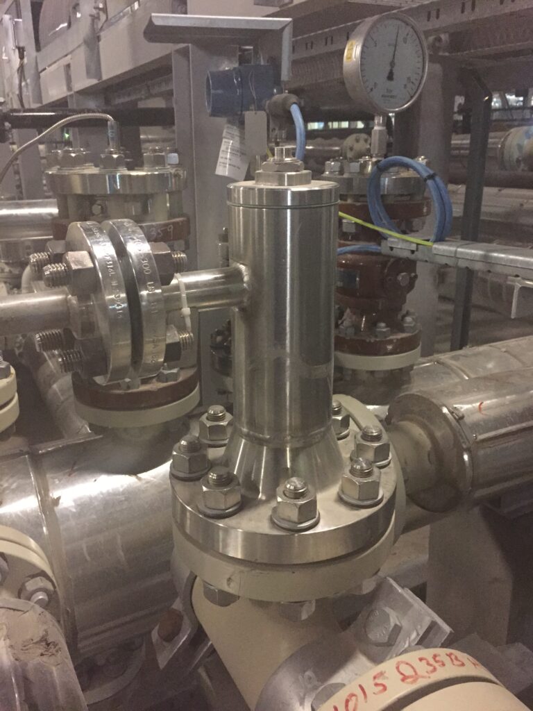
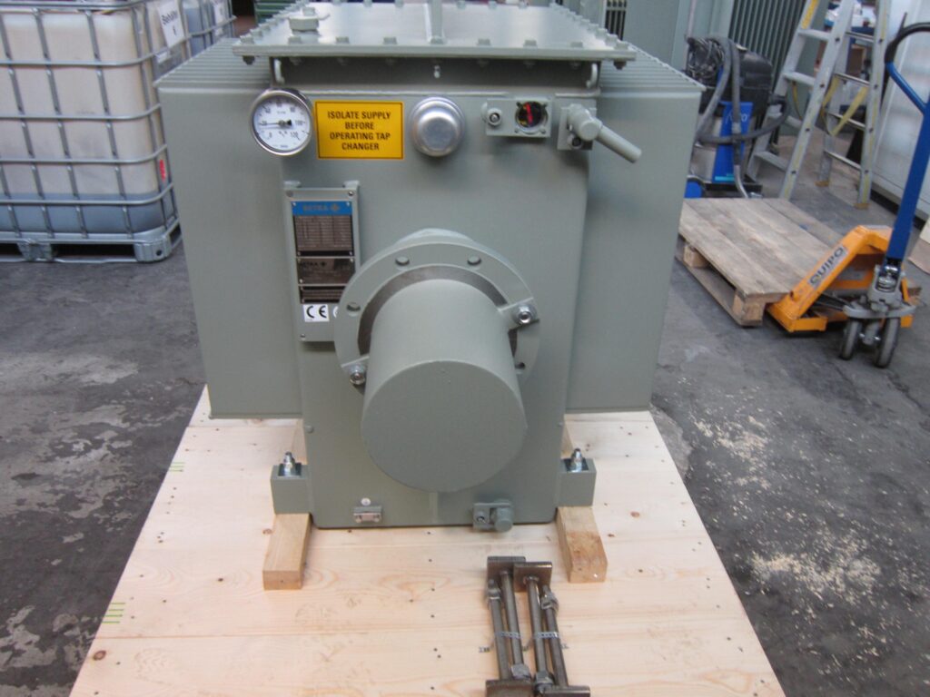
A replacement desalter power unit, also called a desalter transformer, made to order from the nameplate of the unit it replaces: alternating current output on off-load taps, 100 % reactance, rated for the hazardous area, and supplied with the transformer bushing and the oil-filled bushing housing that connect it to the vessel entrance bushing.

Typical AC output taps on the off-load tap changer; other voltages and ratings to order
14 to 22 kV
Limits the current when a wet slug makes the emulsion between the grids conduct
100 % reactance
Fits desalter and dehydrator vessels of several makes, matched from the nameplate and drawings
Any make

Request a quote How a desalter power unit is designed

Spare part

Energises the electrode grid of a crude oil desalter or dehydrator (electrostatic coalescer). The desalter power unit, also called the desalter transformer, is an oil-filled, hazardous-area transformer with 100 % reactance that steps the plant supply up to an alternating current (AC) output for the grid and limits the current when the emulsion conducts. The output is selected on an off-load tap changer, typically 14, 16, 18, 20 or 22 kV; the supply is isolated before the tap changer is operated. Delivered with the transformer bushing and the oil-filled bushing housing that connects to the vessel entrance bushing.

SKU
AH-EC-1009
Condition
New
Status
Made to order
Indicative lead time
On application

Add to enquiry: Desalter power unit

Desalter transformer

What a desalter power unit does

A desalter power unit, also called a desalter transformer, is the oil-filled step-up transformer mounted on or beside a crude oil desalter or dehydrator. It takes the plant supply and delivers an alternating current output of 14 to 22 kV to the electrode grid inside the vessel, where the field makes the dispersed water droplets coalesce and settle.

It is built for a load that short-circuits. Whenever a wet slug or a rising water interface reaches the grid, the emulsion conducts; a winding with 100 % reactance limits the current to about its rated value, the voltage folds back, the slug passes and the field recovers without a trip. The tank is rated for the hazardous area around the vessel and needs no external cooling.

How the power unit is specified

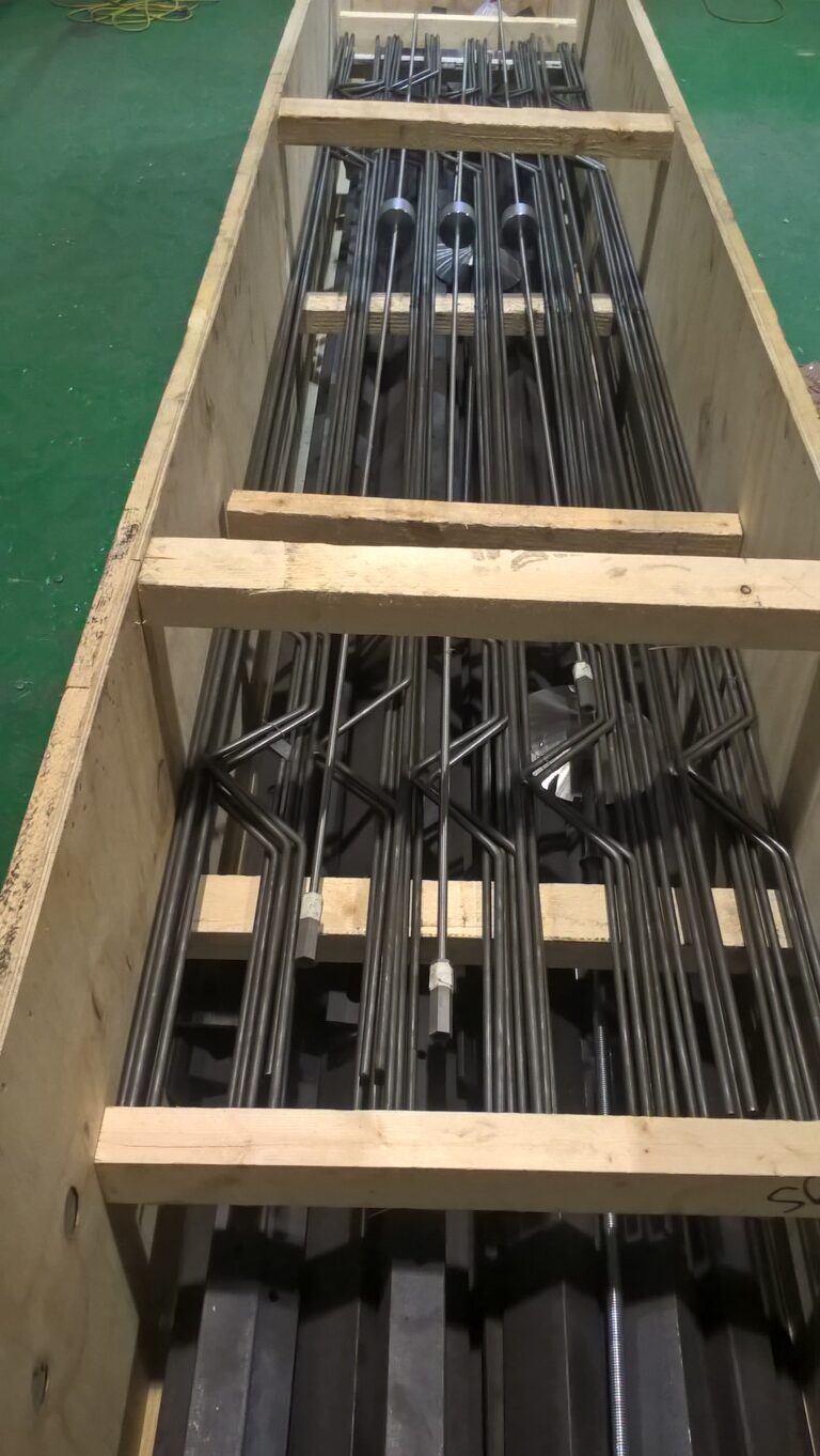
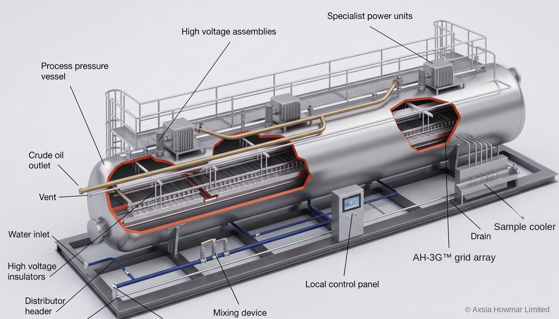
Cutaway model of an electrostatic desalter: the power units on top energise the electrode grid array through the high-voltage assemblies and entrance bushings; the grids hang from the shell on electrode insulators.

Tap changer

Setting the grid voltage: 14, 16, 18, 20 or 22 kV

The output voltage is selected on an off-load tap changer on the tank. The higher taps give a stronger field for heavy or viscous crudes; the lower taps are used where the crude is conductive or the water cut is high and the unit would otherwise run at its current limit. Each tap is a fixed step, so the unit can be matched to the crude and to the grid spacing of the vessel without a change of transformer.

Units are made to order to the rating, supply voltage and output voltages on the nameplate of the unit being replaced; other tappings and ratings are made to order.

The tap changer is an off-load device: the supply is isolated and the unit discharged before a tap is changed.

Desalter bushings

From the transformer bushing to the entrance bushing and the grid

The high voltage reaches the grid through a chain of insulated parts, each of which is supplied as a spare: the transformer bushing on the tank, the high-pressure entrance bushing through the vessel wall, and the electrode insulators that hang the grid from the shell.

  1. Transformer bushingThe high-voltage conductor leaves the oil-filled tank through a bushing on its front face.
  2. Bushing housingA tee spool piece filled with insulating oil, bolted to the transformer and to the vessel, carries the conductor through 90 degrees with no live part exposed in the hazardous area. Its third leg is blind-flanged for making up and inspecting the connection.
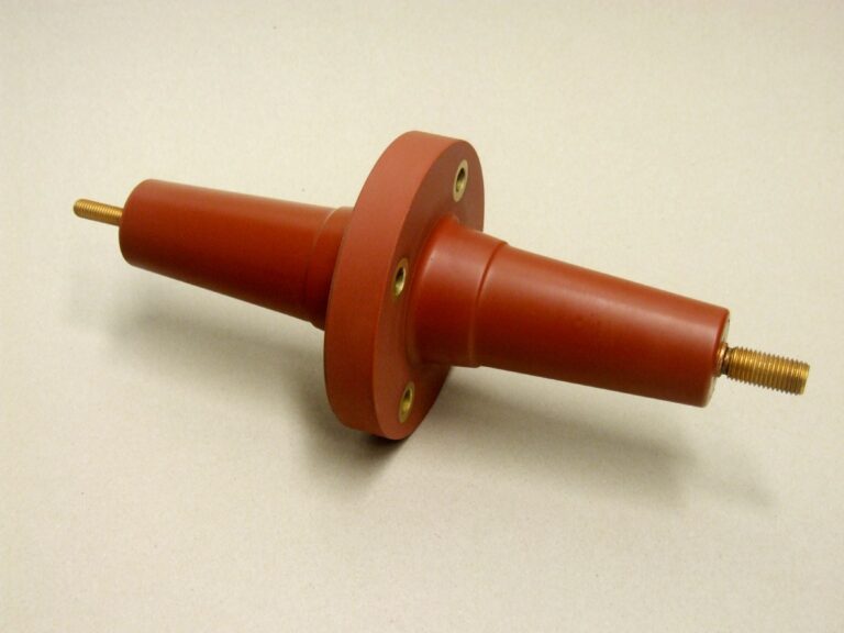
  3. Entrance bushingThe desalter bushing proper: it crosses the vessel wall at process pressure and temperature and connects to the grid through the connecting rod. It is both a pressure part and an insulator.
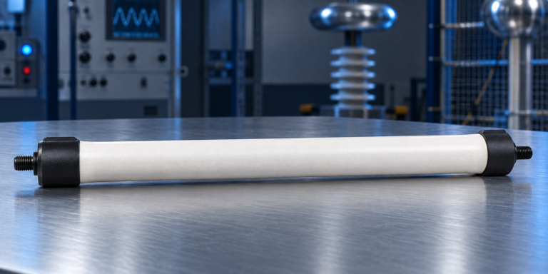
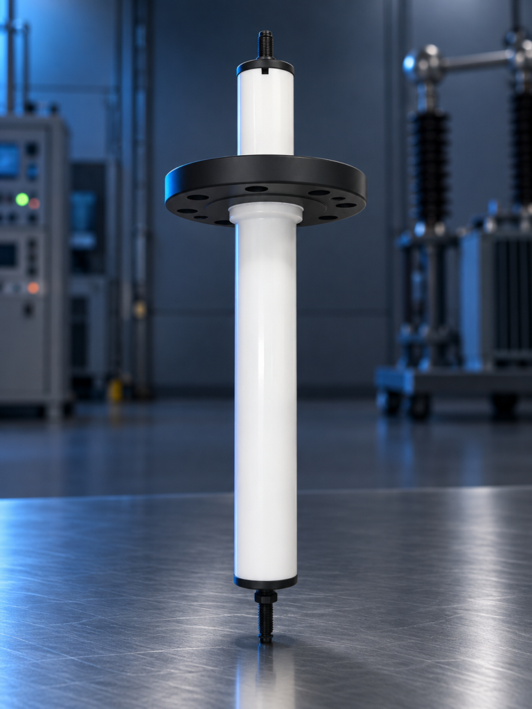
  4. Electrode insulatorInsulators hang the energised grid from the earthed shell and hold the grid spacing that the field strength depends on.

What we need

Four things that identify a replacement desalter transformer

A nameplate photo is enough to start. Send what you have and we will ask for the rest.

  • Nameplate

    Rating in kVA, supply voltage and frequency, output voltage and tappings, maker and serial number.

  • Hazardous-area marking

    The zone, gas group and temperature class the unit is certified for, from the nameplate or the area classification drawing.

  • Vessel and bushing housing drawing

    Mounting arrangement, the flange the bushing housing bolts to and the entrance bushing it connects to.

  • Photos of the existing unit

    The tank, the tap changer, the bushing housing and the connection to the vessel, so that the replacement fits without site modification.

When a desalter power unit is replaced

Desalter transformers run for decades, so replacement is usually driven by one of four things: a winding or transformer bushing failure, an oil leak from a tank that has corroded, obsolescence when the original maker no longer supports the unit, or a change of duty when the grids are replaced or the crude changes and the rated power or the tappings no longer suit the vessel. In the last case the design review sets the new rating before the unit is ordered.

A replacement is made to the nameplate of the existing unit and the vessel drawings, so that it bolts to the same mounting and the same bushing housing flange and no site modification is needed. Where the entrance bushing or the electrode insulators are also due, they are quoted together so that the whole high-voltage path is renewed in one shutdown.
Fit and interchange

Compatibility

Made to order from the nameplate of the existing unit and the vessel drawings: rating in kVA, supply voltage and frequency, output voltage and tappings, hazardous-area marking, mounting and bushing housing dimensions, and the entrance bushing (desalter bushing) the housing connects to. Other output voltages and ratings are made to order. Suitable as a replacement on desalter and dehydrator vessels of several makes; see the compatibility statement below.

Suitable for use with Betra equipment. Not an OEM part unless stated in our quotation. Betra is referenced only to identify compatibility; all trademarks belong to their respective owners.

Compliance

Standards and documentation

Documentation available with supply

  • Certificate of conformity
  • High-voltage / dielectric test certificate
  • Certificate of origin

Information on this page is indicative. Final suitability and compatibility must be confirmed against your equipment, its serial or tag data and its operating conditions before order. Lead-time bands are indicative and are confirmed at quotation.

Questions engineers ask

Frequently asked questions

Is a desalter transformer the same as a desalter power unit?

Yes. Desalter transformer, desalter power unit and, in older documents, TR set or power pack all describe the oil-filled step-up transformer that energises the electrode grid of a crude oil desalter or dehydrator. We use power unit for the complete assembly: the transformer with its tap changer, the transformer bushing and the oil-filled bushing housing that connects it to the vessel entrance bushing.

Why is the output AC on a desalter but DC on a prewash coalescer?

A crude oil desalter treats a water-in-oil emulsion, where the alternating field on 14 to 22 kV taps is enough to make the water droplets coalesce, and the 100 % reactance winding rides through the short circuits that wet slugs cause. An electrostatic coalescer prewash on a kerosene sweetening unit treats a much cleaner, less conductive stream and uses a rectified output varied continuously from 0 to 40,000 V DC by a transformer voltage regulator. The two units are not interchangeable.

Which desalter bushings and insulators go with the power unit?

Three insulated parts carry the high voltage to the grid, and each is supplied separately: the transformer bushing on the tank (AH-EC-1006), the high-pressure entrance bushing through the vessel wall (AH-EC-1001) and the electrode insulators that hang the grid from the shell (AH-EC-1002). Bushings are matched to the nozzle size, flange rating and voltage of the vessel, so send the vessel nameplate and a photo of the existing bushing with the transformer nameplate.

The power unit keeps tripping: does it need replacing?

Usually not. Repeated tripping points to a process cause inside the vessel, such as water carry-over, a high interface or a failed entrance bushing, rather than to the transformer itself. A unit with 100 % reactance is designed to ride through short circuits at its current limit; if it trips on overcurrent or oil temperature, start with the symptom index under troubleshooting before ordering a replacement.

Only have a nameplate photo, a tag number or a drawing reference?

That is enough to start. Send what you have for a desalter, dehydrator, electrostatic coalescer or hydrogen adsorption unit, whoever built it, and we will identify the equipment and the parts it needs. Final compatibility is always confirmed against your equipment data and operating conditions.