Crude oil treatment

Crude oil dehydrators

A crude oil dehydrator is an electrostatic coalescer used to remove produced water from crude so that it meets its basic sediment and water (BS&W) specification. It is the same equipment as a desalter, without wash water. This page covers what is specific to dehydrator duty; the equipment itself is described on the electrostatic coalescers page.

Typical basic sediment and water (BS&W) specification for treated crude
0.1 to 0.2 % vol
Typical electrostatic field across the electrode grids
About 20 kV
The usual reason a dehydrator falls behind its design as a field ages
Rising water cut

Send a technical enquiry The electrostatic coalescer

How it works: Crude oil dehydrators

  1. Free water is removed upstream

    Separators or a free-water knockout take out water that settles on its own, so the dehydrator receives emulsified water only, at a water cut the grids can tolerate.

  2. The crude is heated to treating temperature

    Heat lowers viscosity so that coalesced drops can settle within the residence time available.

  3. Demulsifier weakens the droplet film

    A demulsifier, selected by bottle test, displaces the natural surfactants that keep droplets apart.

  4. The electric field coalesces the droplets

    Droplets polarise, collide and merge in the field between the electrode grids.

  5. Water settles and is drawn off

    Water leaves under interface control. Dry crude leaves from the top of the vessel.

Dehydrator duty

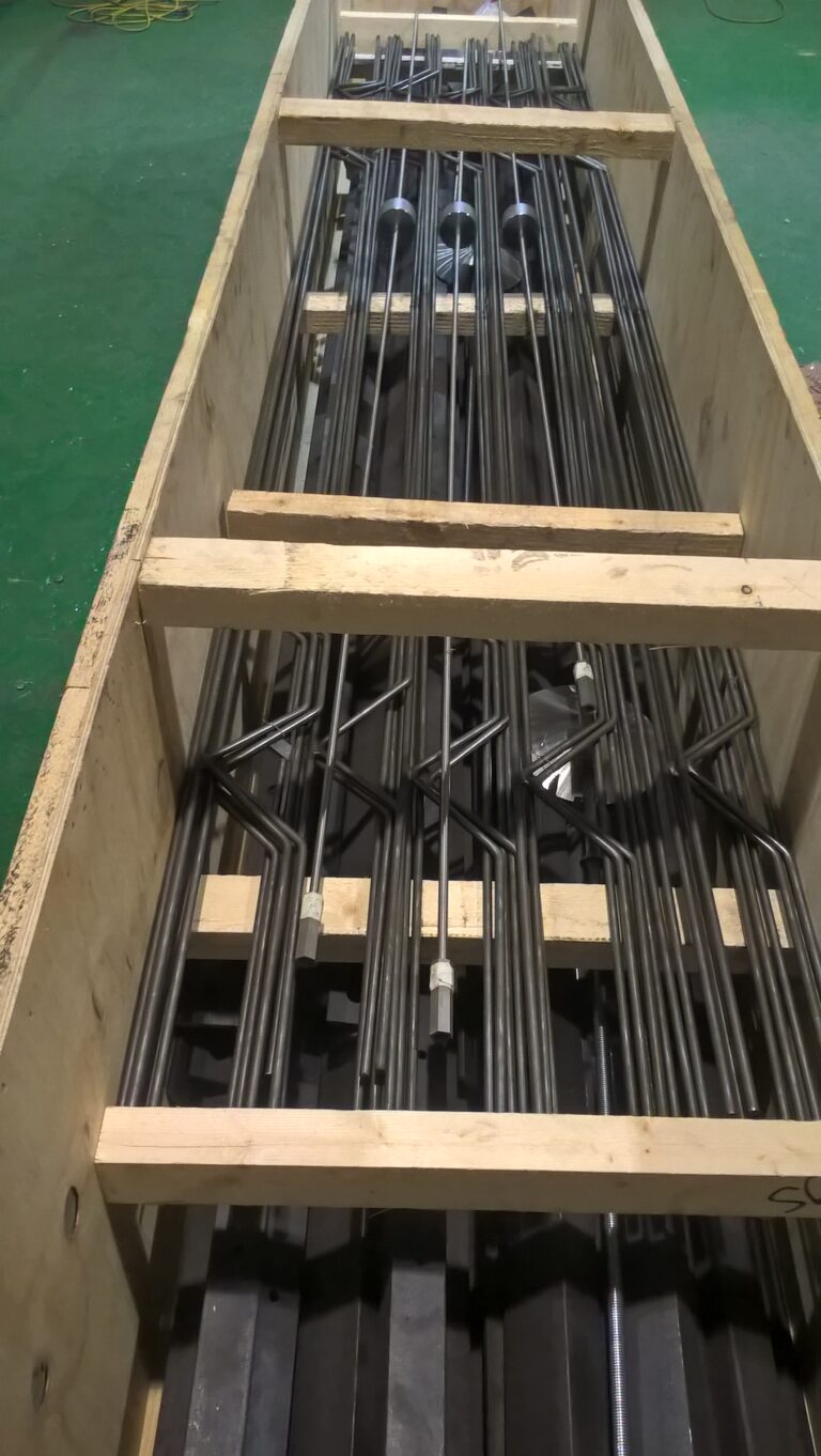
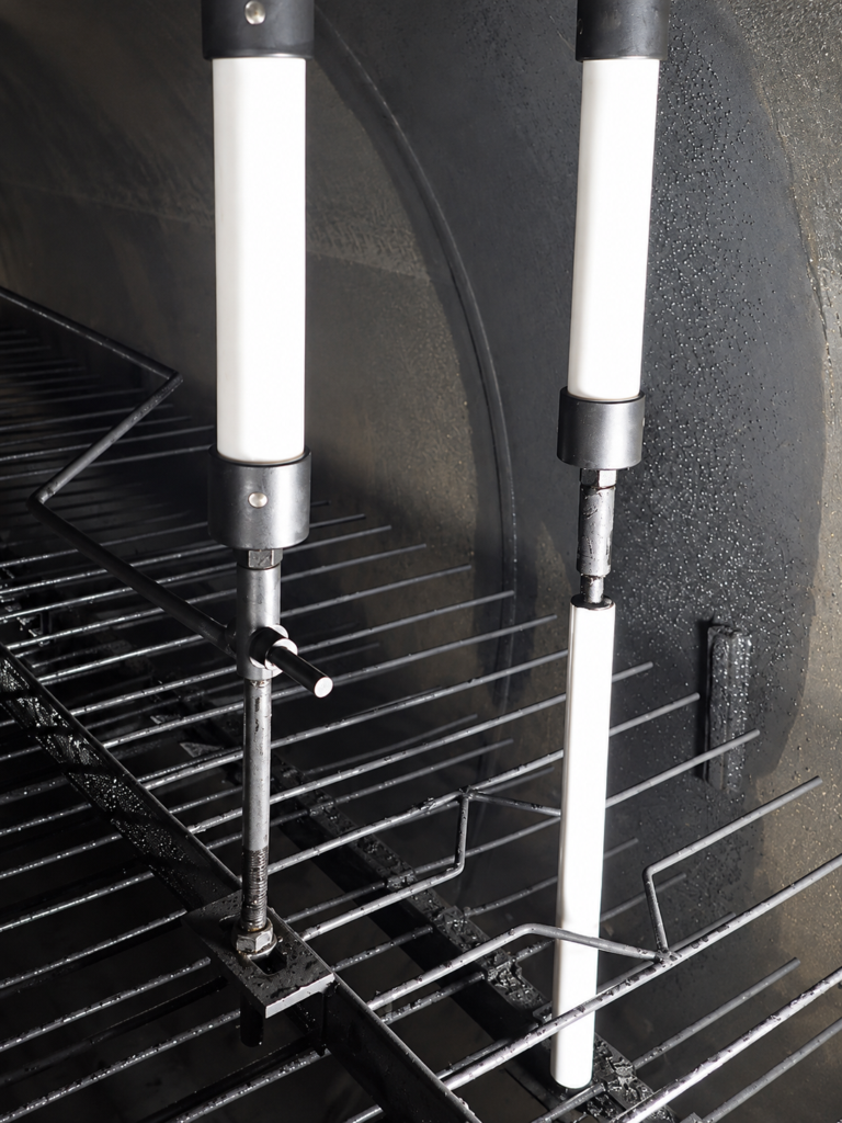
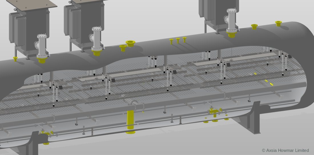
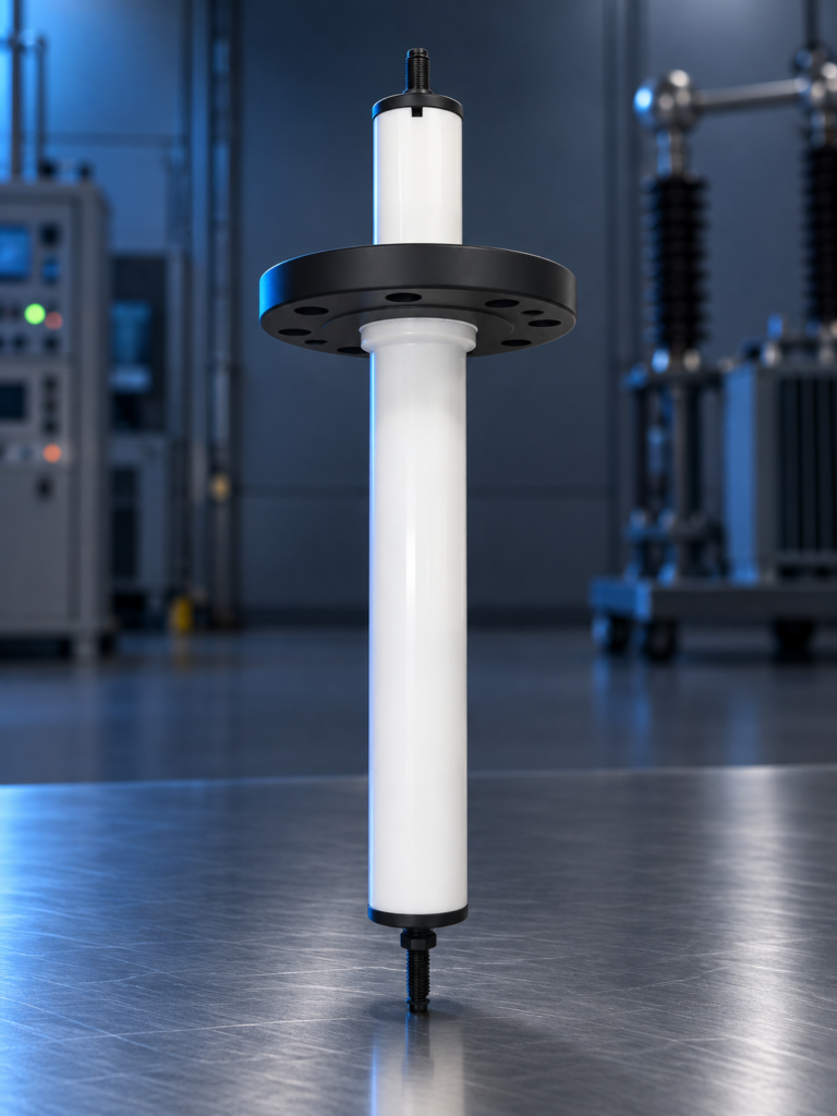
Inside the dehydrator: electrode grids hung on insulators

A dehydrator is an electrostatic coalescer removing produced water without wash water. Heated crude enters through a distributor below the electrode grids, the field polarises the water droplets so that they collide and merge, and the drops settle to the water phase at the bottom of the vessel. Dry crude leaves from the top to the desalter, to storage or to export.

Components, grids and power units

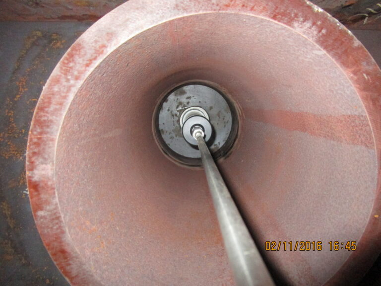
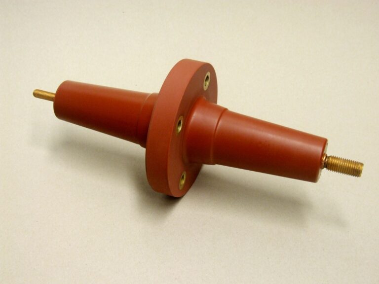
Section through a three-grid electrostatic coalescer: three power units and entrance bushings on the vessel, and the electrode grids hung on insulators above the distributor.

When water cut rises

Three ways to keep a dehydrator ahead of a wetter field

  1. Restore the design temperatureMore water takes more heat; a heater that is short of duty shows up first as high BS&W at the dehydrator outlet.
  2. Upgrade the internalsA different grid arrangement or power units within the existing shell raises the throughput the vessel can treat.
  3. Take the free water out firstA free-water knock-out or better separation upstream keeps the dehydrator for the emulsified water it was designed for.

What is specific to dehydrator duty

Dehydrator duty differs from desalter duty in three ways. No wash water or mixing valve is used, so the emulsion arriving at the vessel is the natural one, not one created by mixing. The inlet water cut is higher and more variable, because it follows the wells. And the target is a water content, not a salt content, although salt falls in step because it is dissolved in the water removed.

The vessel, grids, entrance bushing and power unit are the same as in desalter duty. They are described, with an annotated drawing, on the electrostatic coalescers page.

Where a crude oil dehydrator sits in the process

A crude oil dehydrator sits after the low-pressure separator and the heater, and before storage, export pumps or a desalter stage. Gas must be released upstream: gas breaking out inside an electrostatic vessel disturbs settling and can create a hazard around the energised grids, which is why operating pressure is kept above the crude’s vapour pressure at treating temperature.

Design considerations for dehydrator duty

The design of a dehydrator duty turns on the water cut profile over field life. A unit sized for early-life water cut will be overloaded later, so the design basis should state the maximum water cut the grids must tolerate and the point at which upstream free-water removal is added. The other inputs are viscosity at treating temperature, emulsion stability from bottle tests, solids loading and the BS&W specification.

Heating is the main operating cost of dehydration. The treating temperature is chosen as the lowest that meets specification with a sensible demulsifier dose, because every extra degree costs fuel and drives light ends into the gas phase. See crude oil heaters.

Common operating problems in dehydrator duty

The common operating problems in dehydrator duty are high outlet BS&W, grid voltage collapsing when a wet slug arrives, and rag layer growth fed by solids and production chemicals. Slugging from upstream separators is a frequent root cause, because it changes water cut and flow faster than interface control can follow. Symptoms, probable causes and the data needed to confirm them are in the troubleshooting symptom index.

Revamp options when water cut rises

When water cut rises beyond the design basis of a dehydrator, the options are to remove more free water upstream, raise treating temperature, upgrade the grids and power unit within the existing shell, or add a second vessel. A design review compares these against the forecast water cut, not just today’s.
Design parameters: Crude oil dehydrators

Design parameters: Crude oil dehydrators
ParameterTypical rangeUnitBasis / note
Treating temperature40 to 90°CTypical published range for upstream duty; higher for heavy crude
Operating pressureAbove crude vapour pressure at treating temperaturebargGauge pressure
Electrode voltage, transformer secondary12 to 25kVTypical published range

Typical ranges for orientation only. The design basis for each unit is set from the feed analysis and the required product specification.

Codes and standards applied to Crude oil dehydrators

Typically applied; the governing codes are confirmed per project with the client and the jurisdiction.

ASME BPVC Section VIII Division 1
Pressure vessels Vessel
API 12L
Emulsion treaters Where specified
IEC 60079 / ATEX / IECEx
Equipment for explosive atmospheres Electrical equipment
NACE MR0175 / ISO 15156
Sour service materials Where hydrogen sulphide is present

Applications: Crude oil dehydrators

  • Export and pipeline specification: Bringing produced crude to a BS&W specification such as 0.5 or 0.2 vol% at a production facility.
  • First stage of a desalting train: Removing most of the produced water and salt ahead of a desalter stage.
  • Rising water cut late in field life: Re-rating an existing dehydrator when water cut has moved beyond its design basis.

Scope of supply: Crude oil dehydrators

  • Process design for the dehydration duty (From crude properties, water cut profile and specification)
  • Electrostatic coalescer vessel, internals, power unit and controls (See the electrostatic coalescers page for the full scope)
  • Upstream heater and separators where required
  • Commissioning, start-up support and operator training

Frequently asked questions: Crude oil dehydrators

What BS&W can an electrostatic dehydrator achieve?

An electrostatic dehydrator is normally designed for an outlet basic sediment and water content at or below the sales specification, commonly 0.5 or 0.2 vol%. What a given unit reaches depends on crude viscosity at treating temperature, inlet water cut, emulsion stability and grid loading, so the target is set per project.

What is the difference between a heater treater and an electrostatic dehydrator?

A heater treater relies on heat, chemicals and residence time to separate water. An electrostatic dehydrator adds an electric field, which coalesces droplets far faster than gravity alone. For the same duty the electrostatic unit is smaller or reaches a lower water content, and it usually needs less heat.

How much water can the feed to an electrostatic dehydrator contain?

The feed to an electrostatic dehydrator must stay below the water cut at which the emulsion becomes conductive enough to load the grids. The limit depends on the field type and grid design. Above it, free water is removed upstream first.

Why has BS&W risen at the dehydrator outlet when nothing has changed?

Something has usually changed upstream: water cut, a new well or blend, treating temperature, demulsifier dose, or solids. If the feed is unchanged, the next suspects are a rising emulsion band, low grid voltage, or a fouled or damaged grid. The troubleshooting symptom index lists the checks in order.

Talk to an engineer about your unit

Tell us the equipment, the duty and what you are seeing. Partial data is normal: send what you have and we will tell you what else matters. We acknowledge every enquiry within 1 working day.