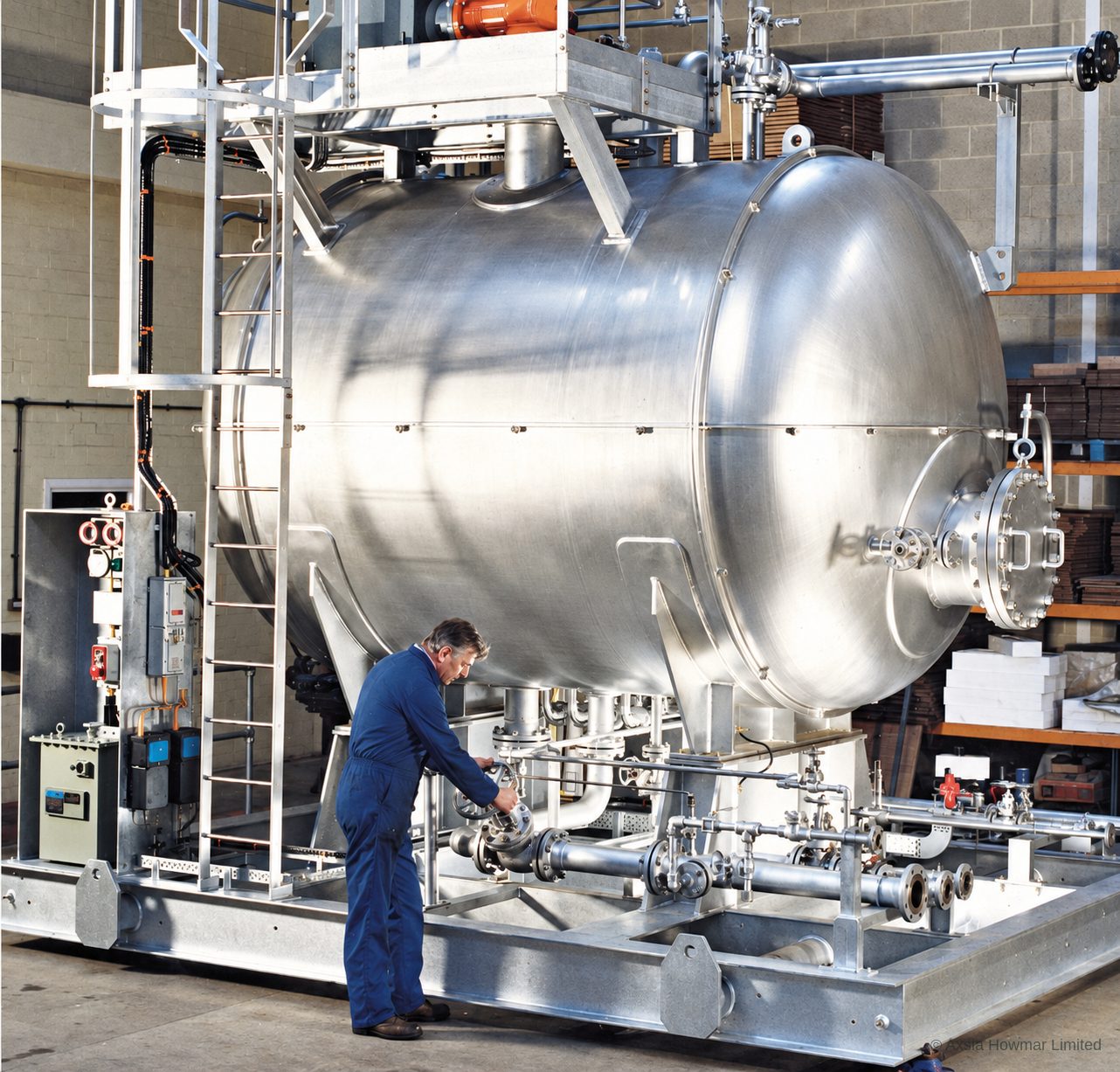
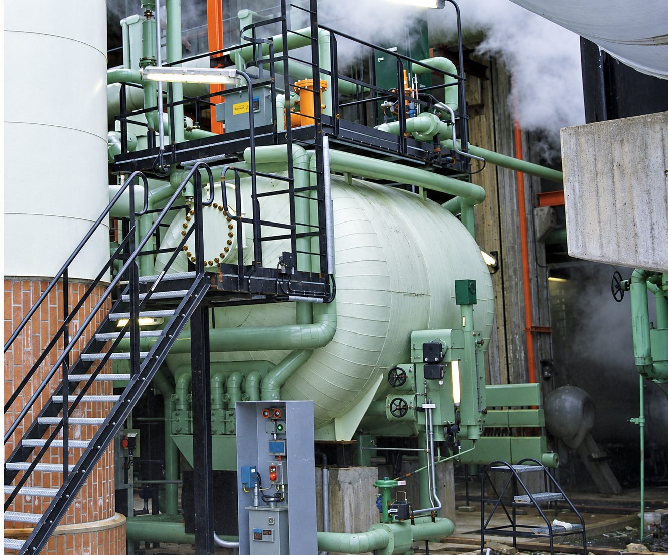
Where the prewash coalescer sits in the process
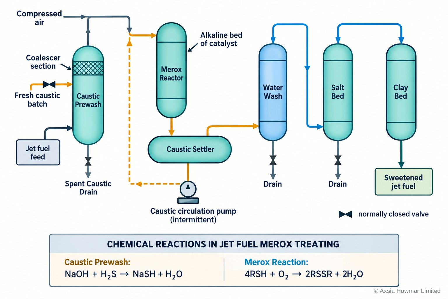
The prewash coalescer sits between the caustic prewash contactor and the mercaptan oxidation (sweetening) reactor of a kerosene treating unit. The prewash removes hydrogen sulphide and naphthenic acids. The coalescer then removes the spent caustic that the kerosene carries out of the contactor, so that the reactor receives kerosene and not a caustic dispersion. It is the same electrostatic principle as the electrostatic coalescers used on crude oil, applied to a clean, low-conductivity product.
Why inlet distribution decides performance
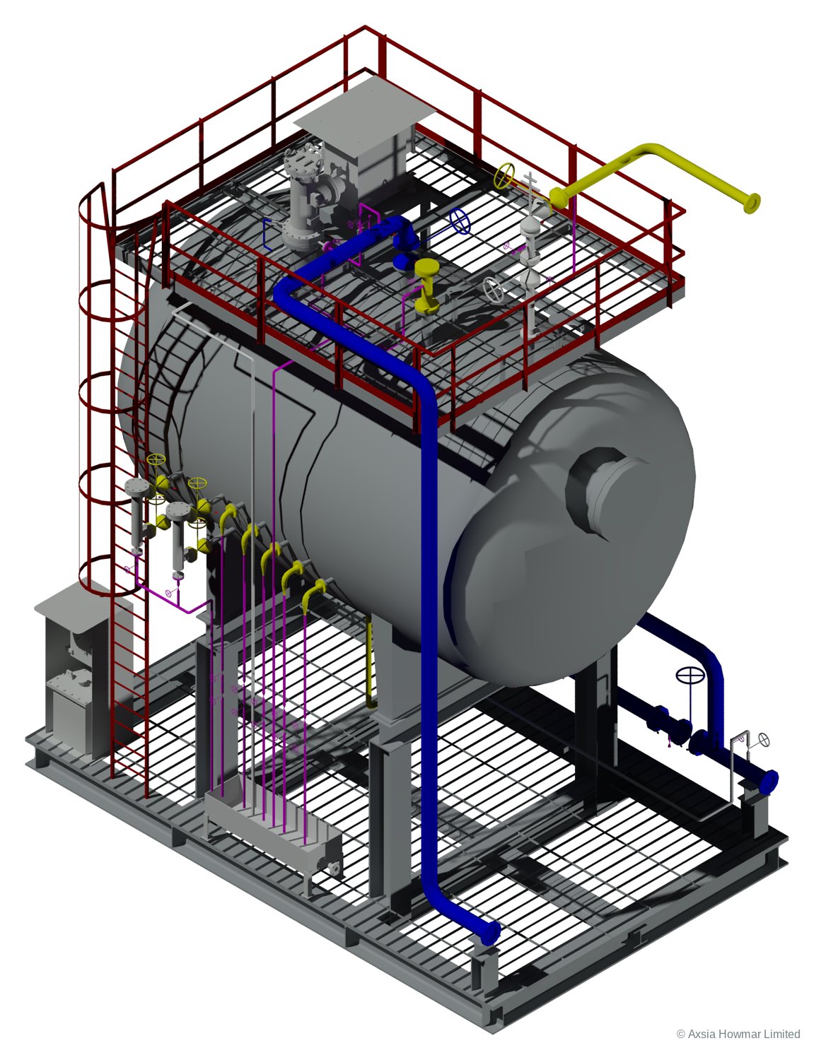
Turbulence and uneven flow at the inlet are the main threats to a prewash coalescer. A jet of kerosene that channels through one part of the electrode grid shortens residence time there, lifts caustic that has already settled, and leaves the rest of the field under-used. Axsia Howmar designs the inlet distributor and outlet collector with a computational fluid dynamics (CFD) model of the whole vessel. The model is iterated until it shows:
- uniform upward velocity across the full cross-section of the electrode grid;
- no short-circuiting from inlet to outlet;
- droplet settling paths that reach the interface at design flow and at turndown;
- no disturbance of the settled caustic layer;
- pressure drop across the distributor and collector within the allowance.
On a retrofit the existing vessel and nozzles are modelled first, so new internals are designed against the flow field the plant actually has.
Design of the main components
Separation depends on how the components work together, so they are designed as one system.
- Power unit. A three-phase low-voltage supply is stepped up and rectified to a steady DC output. A reactive design limits the current drawn during an upset, so the unit stays on line. A voltage controller on the local panel lets the operator set the electrode voltage.
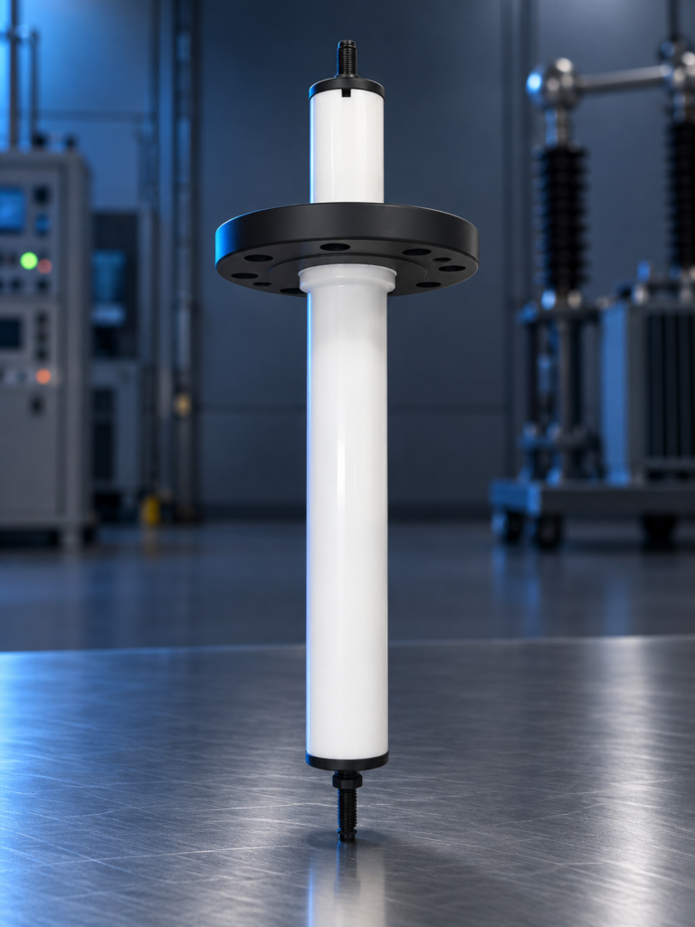
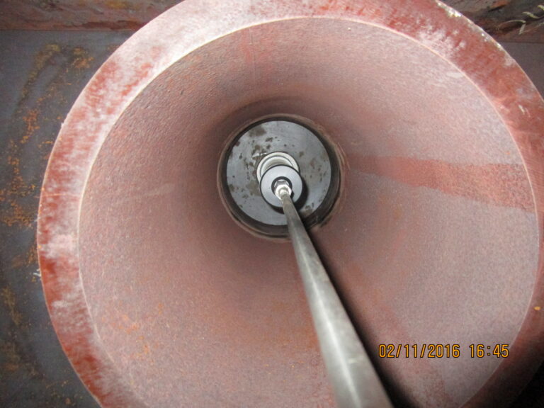
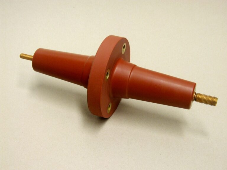
- Entrance bushing. The entrance bushing carries the high-voltage supply through the vessel wall to the electrode grid. It is rated for the design pressure and temperature of the prewash service.
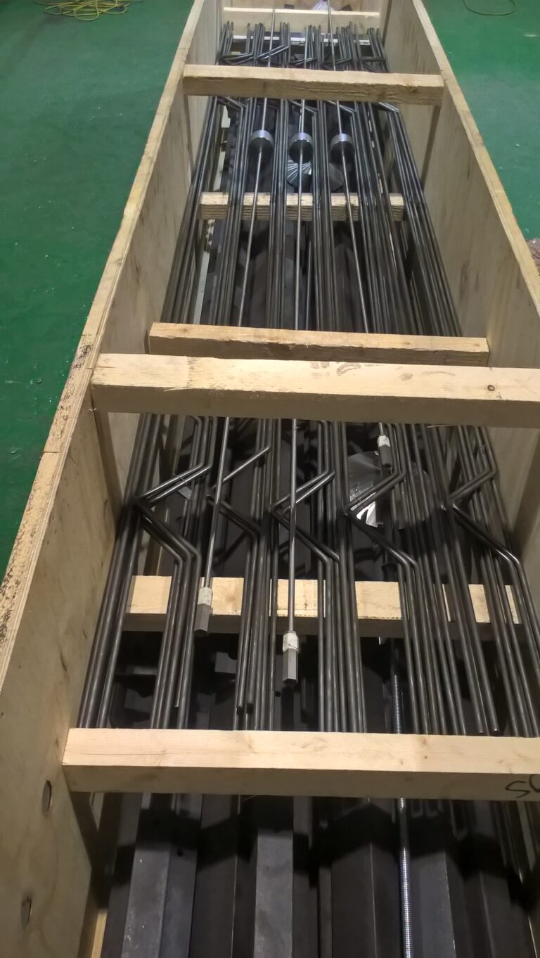
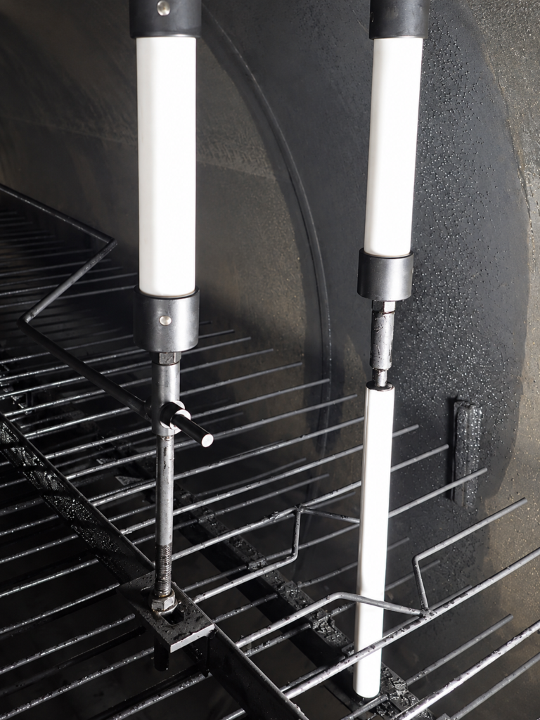
- Electrode grid. The size, orientation and position of the grid in the vessel are set for the caustic-in-kerosene duty, with an open flow path through the field.
- Fluid distribution. The inlet is below the grid and above the normal interface. The outlet collector gives an even draw-off.
- Hazardous area. Electrical equipment is certified for the area classification of the unit location.
Support for installed coalescers and precipitators
Many kerosene treating units run electrostatic coalescers or precipitators supplied decades ago, often by a manufacturer that has closed or been absorbed. Axsia Howmar supports these units in three ways.
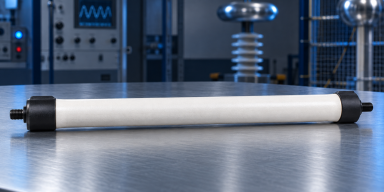
- Assessment and retrofit. Replacement electrode grid and insulators sized to the existing shell, entrance bushings matched to existing nozzles, a new power unit with voltage control, and distributor and collector upgrades designed from a CFD model of the existing vessel. An ageing precipitator or settler can be converted to a DC coalescer.
- Troubleshooting. Caustic carryover, power unit trips, low field voltage and interface problems usually trace to a small number of electrical, process or mechanical causes. See troubleshooting and performance diagnostics.
- Spare parts. Entrance bushings, grid insulators, grid assemblies and hangers, power units and controllers, and distributor internals. Where the original part cannot be obtained, a replacement is engineered from drawings or from the worn part. See prewash coalescer spare parts and legacy equipment spare parts. Parts for equipment built by others are supplied as suitable for that equipment and are not original manufacturer parts unless our quotation says so.
What we look at first on an existing unit
- Vessel dimensions, design pressure (barg) and temperature, nozzle schedule and orientation.
- Original manufacturer, model and year, and the documentation that survives.
- Electrode grid type and condition; insulator and entrance bushing materials.
- Power unit rating, output voltage and controller type.
- Design and current throughput, kerosene properties and caustic strength.
- Interface level control and caustic draw-off routing.
- Hazardous area classification of the unit location.
- Symptoms: carryover, trips, low voltage, catalyst upsets, specification failures.
Most of this can be answered from drawings and operating records before a site visit.
Other clean-product duties
The same DC coalescer design is used to remove water or aqueous treating solutions from other low-conductivity products, such as gas condensate, liquefied petroleum gas (LPG), naphtha, jet fuel and diesel.
Talk to an engineer about your unit
Tell us the equipment, the duty and what you are seeing. Partial data is normal: send what you have and we will tell you what else matters. We acknowledge every enquiry within 1 working day.