
Why a rate-based model, and what it solves
Catalogue scrubbers are sized by rules of thumb: a bed height, a liquid rate, a mesh pad. That is enough when the specification is a visual one. It is not enough when the specification is a potassium concentration in condensate, because the answer is decided by the fraction of the inlet mass that lies below a micrometre, and by how each element treats that fraction. KOH Guard is therefore sized with a one-dimensional, rate-based model of the complete train. It resolves the inlet droplet-size distribution into sixty size classes and follows each class through both packed beds, the mesh pad and the coalescer, and it solves the column hydraulics and the coupled two-loop water and alkali balance at the same time.
The physics is standard and published: Onda, Takeuchi and Okumoto for the wetted area of the packing; impaction, interception and diffusion capture per droplet size, with a deep-bed capture formulation per bed after Tien and Ramarao; the Robbins pressure-drop correlation with the Kister and Gill flood limit for the hydraulics; Souders-Brown for the mesh pad; vendor-type grade-efficiency curves for the mesh pad and the coalescer, characterised by a 50 % cut size and a sharpness; and the dilute-KOH chemistry that gives conductivity and pH in each loop. An independent component mass balance closes every run, and fifteen automatic checks report whether the case sits inside the correlations’ range. Two of those checks are evidence gates that stay open by design until supplier or pilot data for the packing capture and the coalescer grade curve have been accepted for the project.
The inlet: a log-normal mist with a decisive tail
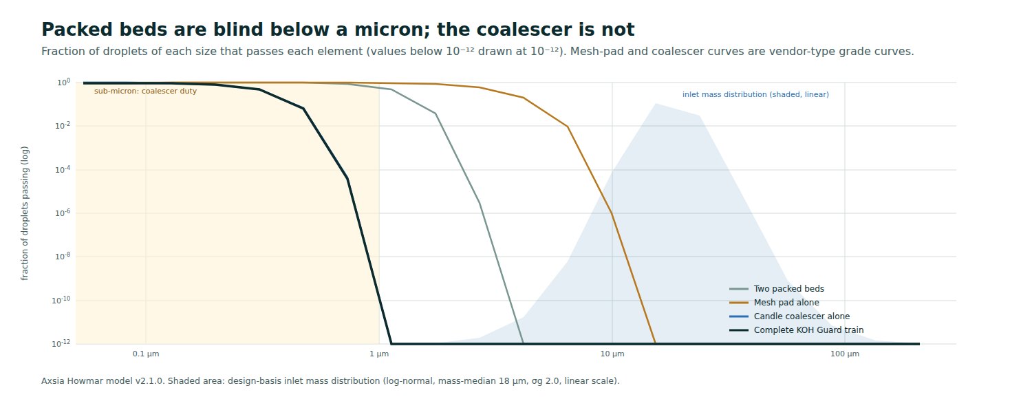
The design basis is a log-normal distribution with a mass-median diameter of 18 µm and a geometric standard deviation of 2.0, in 30 wt% KOH droplets. Most of the mass lies between 5 and 60 µm, where packing captures it easily. Only about 0.5 % of the inlet mass lies below 3 µm, yet that half per cent decides the condensate quality, because it is the fraction that nothing but the coalescer can reach. No public dataset quantifies alkaline-electrolyser carryover in mg/Nm³, so the inlet is taken from the electrolyser supplier’s declaration or from an inlet survey, and the survey replaces the assumed distribution with measured data before design freeze.
What each element contributes
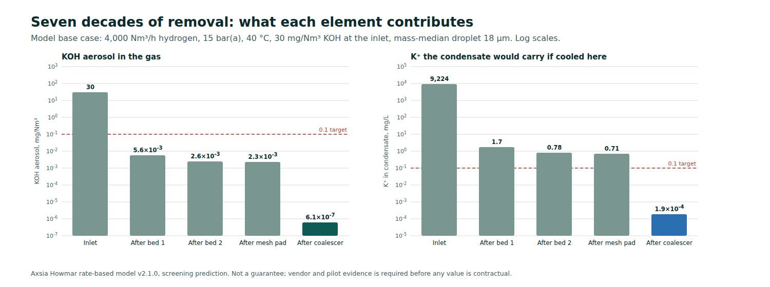
On the base case the first bed removes 99.98 % of the inlet mass, and the first half-metre of it does most of that work. The polish bed then flattens out, because the droplets that survive are too fine for packing: adding height beyond this point buys little, adding a coalescer buys a lot. After the beds and the mesh pad the gas carries about 2 × 10⁻³ mg/Nm³, already inside a 0.1 mg/Nm³ aerosol target, but the condensate it would give is about 0.7 mg/L, seven times above a 0.1 mg/L target. The candle coalescer takes the remaining fine tail to about 6 × 10⁻⁷ mg/Nm³ and 0.0002 mg/L.
Load-following, hydraulics and scale
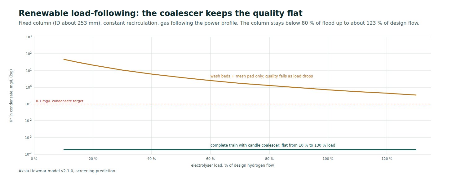
Renewable electrolysers ramp with the power. As the load falls, gas velocity and impaction fall with it and a column on its own lets more mist through. The model screens a fixed column of about 253 mm inside diameter with constant recirculation from 10 % to 130 % of design flow: with the coalescer in place the condensate quality stays flat across the whole range; without it, quality falls steadily as load drops and misses the 0.1 mg/L target everywhere. Hydraulically the design point sits at a gas capacity factor of about 1.85 Pa⁰·⁵, comfortably left of the flood point on the Robbins curve for the design liquid load, and the column stays below the preferred 80 % of flood up to about 123 % of design flow. Final hydraulics are confirmed with the packing supplier’s rating.
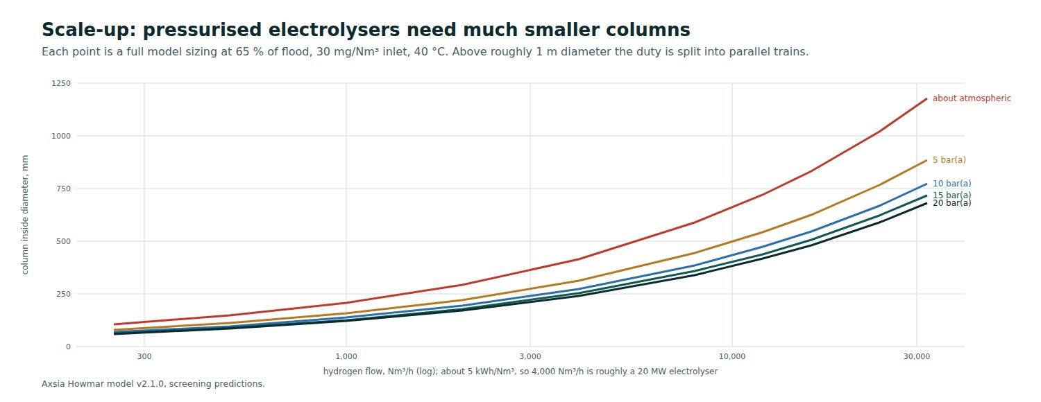
Column diameter grows with the square root of the actual gas volume, so pressure matters more than anything else to the size of the equipment. An atmospheric electrolyser of 160 MW needs a column over a metre in diameter and hundreds of coalescer candles across several housings; a 15 bar unit of the same size needs a column of about 0.5 m and a few dozen candles. Above roughly one metre the duty is split into parallel trains.
Sensitivity, robustness and start-up
A sensitivity sweep of ten inputs shows that two of them dominate the predicted condensate quality: the spread of the inlet droplet distribution and the coalescer’s cut size. Moving the geometric standard deviation from 1.7 to 2.5 changes the answer by more than six orders of magnitude; moving the coalescer cut size from 0.2 to 0.5 µm changes it by three. Column-side choices, bed height, liquid-to-gas ratio and the approach to flood, barely move the final number once the coalescer is in place. That is why the engineering effort goes into characterising the inlet and validating the coalescer rather than into extra packing.
The same model is used as a stress test. If the packed beds capture far less than predicted, with the equivalent collector size multiplied by up to about 21, which takes the capture model from its granular-bed analogy to the hydraulic diameter of the packing channels, the complete train still holds the condensate near 0.0002 mg/L, while a column without a coalescer would miss the target by up to 790 times. A start-up transient from a clean deionised fill shows the lye loop reaching its 5 mS/cm set point after about 11 hours, after which the conductivity-controlled blowdown opens and holds it; the conductivity trend is a live signal of how much KOH the column is capturing.
From prediction to proof
The model’s outputs are a sized column, beds, mesh pad and coalescer; a heat and material balance with loop, make-up and blowdown flows; the hydraulic map, sensitivity sweeps and packing comparison; a results workbook and a design report; and the enquiry basis for the structured packing and the coalescer. Every number is traceable to one run manifest. What the model cannot do is replace evidence. Packing hydraulics come from the supplier’s rating, coalescer suppliers must provide a duty-specific grade-efficiency curve with liquid-loading and drainage limits and wet pressure drop, and the evidence gates close only when that data is accepted. At site, upstream and downstream sampling into deionised-water impingers with ion chromatography or ICP-MS analysis, the method the National Physical Laboratory used to show no potassium above 0.2 µg/g in purified electrolyser hydrogen, closes out the limit, with the condensate sampled after the cooler. A screening prediction is never presented as a validated guarantee.
References
Sources are listed below in the order they are drawn on: the electrolyser operating envelope, the droplet-formation studies, the downstream-damage mechanisms, the fuel-quality standards, the materials guidance and the model correlations.